the Creative Commons Attribution 4.0 License.
the Creative Commons Attribution 4.0 License.
 | 12 Sep 2025
Experimental study on granite-weathered crust landslides with different residual layer thicknesses under heavy rainfall
Jingye Chen
Qinghua Gong
Jun Wang
Shaoxiong Yuan
Landslides are frequent in granite areas during rainfall. The hydrological response and deformation damage mechanisms of granite-weathered crust slopes were investigated by physical model tests. The variability of the material with respect to the thickness of the residual layer was taken into account. The results show that the three types of slopes exhibit distinct disaster mechanisms. For the E1 slope (10 cm residual layer), the residual layer was rapidly saturated, and seepage was formed. The residual soil was susceptible to severe suffosion, and an overall flow-slip failure occurred with no obvious sliding surface. For the E2 slope (20 cm residual layer), rainfall infiltrated the soil–rock interface, forming a temporary water table at this location. The slope tended to slide along the soil–rock interface at the foot of the slope under the traction and drag of water flow. For the E3 slope (30 cm residual layer), rainfall failed to infiltrate the interface, and no seepage was observed within the slope. The slope gradually slides within the residual layer under hydrostatic pressure and self-weight, with a circular arc sliding surface. This study fills the gap in granite-weathered crust landslides with different residual layer thicknesses and has certain theoretical significance.
- Article
(19885 KB) - Full-text XML
- BibTeX
- EndNote


Granite is widely distributed in the southeastern coastal areas of China. The area of granite in Guangdong Province is approximately 65 300 km2, which accounts for about 36 % of the total area of the province (Zhang, 2009). The granite is subject to a lengthy period of physico-chemical weathering to form a huge, thick weathered crust with a surface layer of granite residual soil. The residual soil exhibits superior integrity and remarkable mechanical properties due to the robust interconnections between weathering residues (Heidemann et al., 2021; Lu et al., 2024). However, residual soil exhibits poor hydro-physical characteristics, rendering its original stable structure susceptible to rapid destruction when exposed to water (Branco et al., 2014; Li et al., 2020; Liao et al., 2025). Wang et al. (2020) demonstrated that slope stability is reduced by up to 30 % under wet and dry cycles. Guangdong Province is situated within the subtropical monsoon climate zone, characterized by abundant rainfall. The granite area is prone to mountain disasters occurring during rainfall. In recent years, a number of clustered landslides in this region have been reported (Wang et al., 2023; Yang et al., 2024; Zhang et al., 2025). These disasters have caused considerable economic and ecological losses within the region.
The weathered granite crust exhibits a distinctive layering feature, whereby the upper layer consists of granite residual soil and the lower layer comprises weathered granite, which is an earthy rock. Landslides occurring on this type of slope have been shown to exhibit significant material variability. The present focus of research on the influence of material variability on slope instability is on the difference in the physical properties of single-layer homogeneous landslides. The fine particle content of the soil enhances the likelihood of soil liquefaction and affects landslide failure mechanisms (Monkul and Yamamuro, 2011; Monkul et al., 2016). The initial porosity of the soil has been demonstrated to affect the shear behavior of the soil during slope failure, which in turn affects the failure mode of the landslide (Iverson et al., 2000; McKenna et al., 2011). Density has an impact on the process of rainfall infiltration on slopes, resulting in differences in the hydrological response to rainfall (Lora et al., 2016; Jiang et al., 2017). It is evident that the variability of landslide materials is a key influence on the formation mechanism and damage pattern of landslides, especially when this variability occurs on a single slope. Rahardjo et al. (2012) observed rainfall infiltration on fine sand–granite rubble slopes and, through the utilization of negative pressure monitoring, confirmed that the rubble layer can effectively impede the infiltration of heavy rainfall. The coarse-grained layer can be used as a barrier layer to control rainfall infiltration into the slope to prevent landslides (Krisdani et al., 2010; Chen et al., 2022). Lourenço et al. (2006) modeled soils with different grain size distributions on slopes and found that the slope failure mode depends mainly on the relative stratification. The slope seepage pattern, influenced by the relative stratification, changes the pore water pressure response characteristics of the slope. This, in turn, affects the slope failure mode. Bian et al. (2024) simulated the hydrological evolution of non-homogeneous slopes under rainfall conditions by means of a flume test. It was found that differences in the soil permeability within the slope resulted in the existence of a relatively dry–wet interface. Changes in the strength properties of the material on either side of this interface created conditions for deep-seated landslides. It can be seen that considering the soil variability of individual slopes leads to a better understanding of the landslide damage mechanism (Wu et al., 2019; Ng et al., 2021). However, the majority of current research on granite-weathered crust landslides has been confined to the variability of the physical properties of a single material, such as the effect of grain size distribution and dry density on slope hydrology and damage processes (Xu et al., 2018; Hu et al., 2020; Wu et al., 2022). Meanwhile, the weathering degree of granite is influenced by geomorphological and climatic conditions, which results in residual layers with significant thickness differences (Qi et al., 2022). Consequently, it is imperative to consider the influence of material variability and the thickness of residual layers when attempting to elucidate the slope damage in granite areas under heavy rainfall.
In this study, a detailed survey of the study area was conducted first. On this basis, three granite-weathered crust slopes with different residual layer thicknesses were designed and modeled under rainfall conditions. The tests used water content sensors, pore water pressure sensors, and soil pressure sensors to monitor the hydrological response and mechanical behavior of slopes during rainfall. The process of generation and development of slope cracks, erosion, and damage during rainfall was studied by taking photographs. Combined with the sensor monitoring data, the changes in water content, pore water pressure, and sliding thrust at different locations of slopes were analyzed, which further revealed the deformation and damage mechanism of granite weathering crust slopes with different residual layer thicknesses under heavy rainfall. This study can provide a theoretical basis for the monitoring and prevention of rainfall-induced landslides in granite areas.
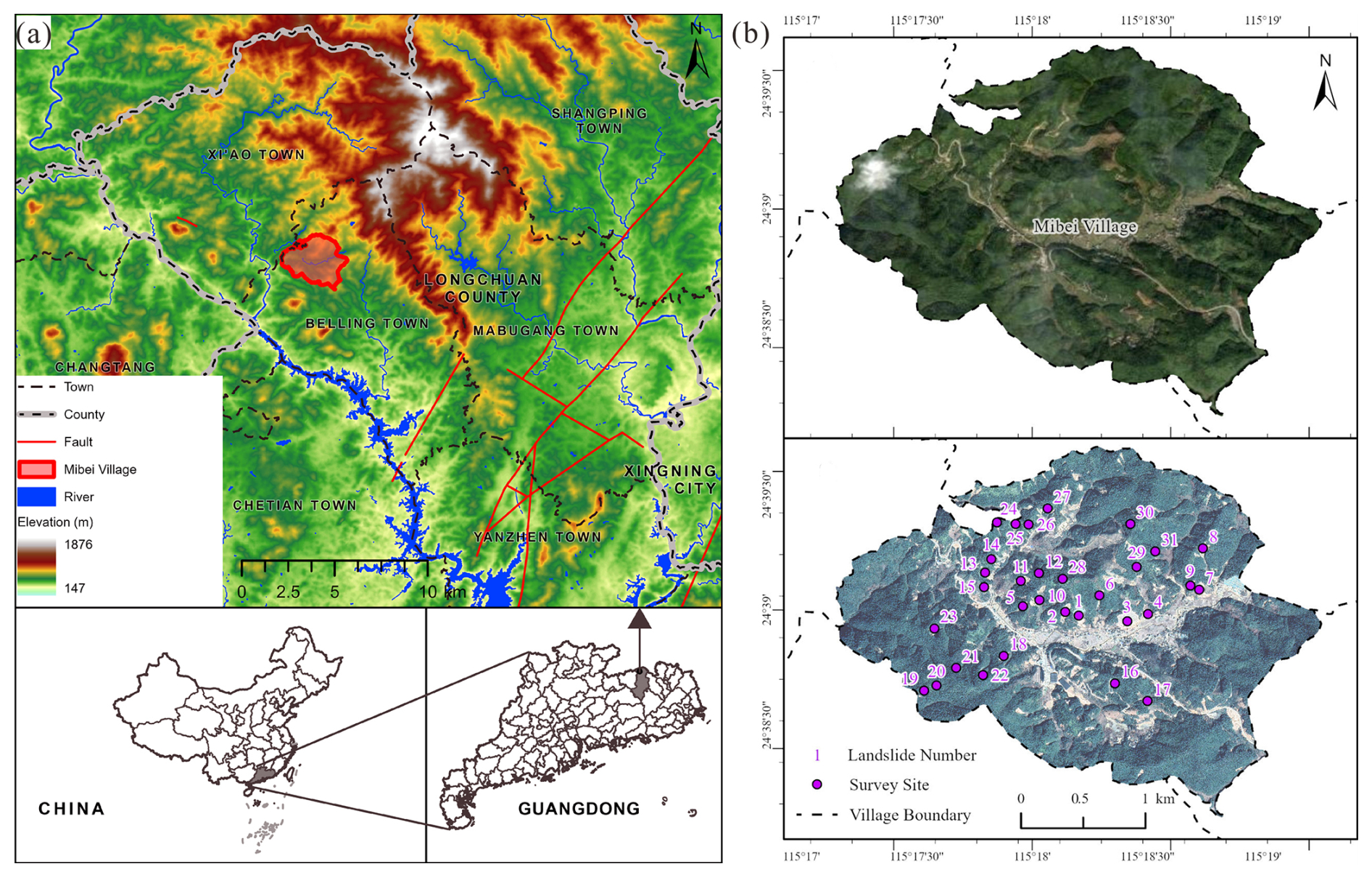
Figure 1Map showing the background of the study area. (a) Geographical location. (b) Satellite images before and after the disaster (©Google Earth 2022). Publisher's remark: please note that the above figure contains disputed territories.
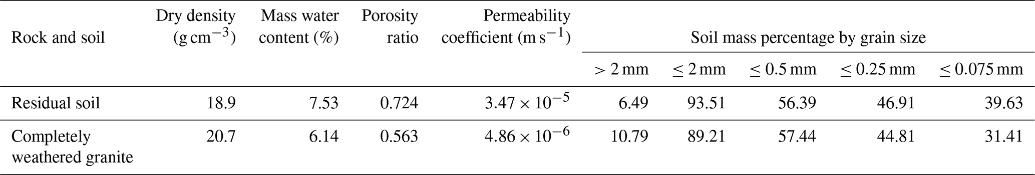
Longchuan County, Guangdong Province, is located in the subtropical monsoon climate zone of China. The area experiences a high level of precipitation, with an average annual rainfall of 1621.79 mm. The distribution of rainfall across the region is uneven, with the majority of precipitation occurring between April and July each year. These months account for 52 % of the annual rainfall, with the majority of this occurring as heavy rainfall. A total of 95.35 % of geohazards occurred during periods of concentrated rainfall (Jia et al., 2024). There is a strong correlation between periods of heavy rainfall and periods of high incidence of geohazards. From 10 to 13 June 2019, persistent rainfall occurred in Longchuan County. One of the heavy rainfall events from 14:00 to 19:00 UTC+8 on 11 June resulted in mass landslides throughout the village of Mibei. Following the disaster, we surveyed the geological and geographic environment of the village of Mibei, focusing on the 31 larger landslide sites in this event (Fig. 1b). The study area is a hilly and mountainous landform with simple geological conditions. There are no discernible faults or folds, and the groundwater table is deep. The bedrock consists of Lower Paleozoic granite. The outcrops on the surface expose the thick, weathered crust formed by the weathering of granite. A distinct boundary can be seen in the profile of the stratum (Fig. 2a), showing a typical dual structure. The upper part of the weathered crust is the residual layer formed in situ after the weathering of granite. It is unevenly exposed at different locations and has a thickness of 1.00–10.40 m. The residual soil is hard plastic, slightly wet, and yellowish-brown in color. Quartz grains are visible to the naked eye. The lower part consists of the completely weathered layer, where the original rock structure remains discernible. The lower part of the weathered crust is the completely weathered layer, where the original rock structure remains recognizable. The completely weathered granite is hard and grayish-brown in color. All minerals, except for quartz, have been weathered (Fig. 2b). The basic geotechnical properties of the weathered crust are shown in Table 1. According to engineering classification, the residual soil belongs to sandy clay. The lower, completely weathered layer is more compact and less susceptible to water seepage than the upper residual layer. The survey statistics of 31 landslide points show that the slope gradient of the landslides ranges from 31 to 45°, with the transverse width from 36 to 135 m and the longitudinal length from 40 to 88 m. The sliding surface depth ranges from 1.5 to 4.3 m, all of which are shallow landslides. The material composition of the landslide mass is mainly residual soil. The water content of the landslide mass is considerable, and some of the landslides exhibit fluidization.
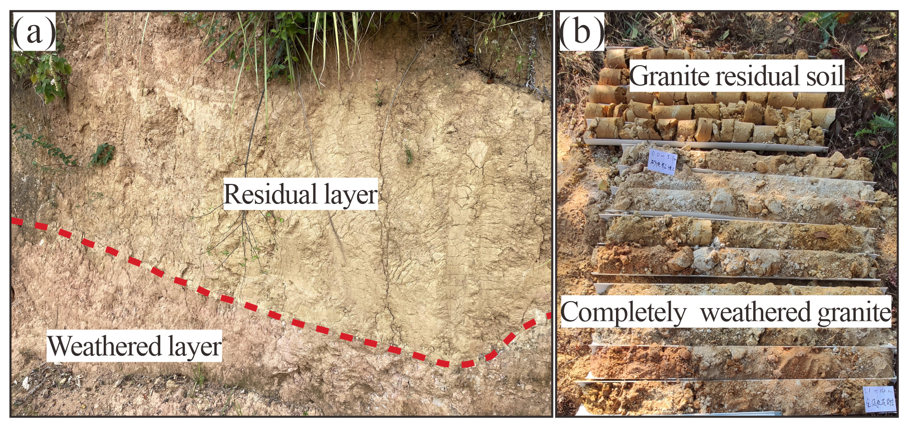
Figure 2Geological condition of the study area. (a) Stratigraphic structure. (b) Drill core samples.
3.1 Artificial rainfall model test
The slope physical model test platform is comprised of a model box, a rainfall system, and a data acquisition system (Fig. 3a). The dimension of the model box is 2 m × 1 m × 1.8 m (length × width × height), and it is constructed with Plexiglas and steel columns. Grid lines have been drawn on the Plexiglas sidewalls to provide coordinate reference and datum control. The EL-RS3/5 mobile artificial rainfall simulation system produced by the Beijing ECO-LEADER company consists of a rainfall machine, a water supply system, and a control system. Its effective rainfall area is 5 m × 3 m (length × width), with the rainfall uniformity coefficient greater than 0.9. The data acquisition system mainly consists of water content sensors, pore water pressure sensors, soil pressure sensors, and a data collector, which are produced by Xi'an Weizheng Electronic Technology Company. Two layers of sensors were buried at the foot, middle, and top of the slope, respectively, and the specific location is shown in Fig. 4. The sensor data are transferred to the notebook at a frequency of 3 min via the data collector. The deformation damage characteristics of slopes are recorded using the camera.
The objective of this test is to explore the rainfall infiltration law and the process of deformation damage in granite-weathered crust slopes with varying residual layer thicknesses during heavy rainfall. A slope model geometric similarity ratio of 1:20 was determined based on the field investigation and test conditions. The model measures 120 cm in length and 100 cm in width and has a slope angle of 30°. The depth of the sliding surface and the thickness of the corresponding residual layer were measured for 21 landslides (the positions are plotted in Fig. 1b, and the data are listed in Table 2). The thickness of the residual layer is primarily concentrated at 1.83–2.14, 3.66–4.20, and 5.72–6.42 m, respectively. Consequently, the midpoint values of these three intervals, 2, 4, and 6 m, were selected for the study. According to the geometric similarity ratio, three sets of test models, designated E1, E2, and E3, were designed with residual layer thicknesses of 10, 20, and 30 cm, respectively. The generalized geological model is shown in Fig. 4. According to the Weber similarity criterion, the rainfall intensity similarity ratio should be the negative one-half power of the geometric similarity ratio (Sun and Zhang, 2012). Accordingly, this study employs the rainfall intensity similarity ratio of 1:0.22. The cumulative rainfall in the study area prior to the disaster was 62.4 mm from 14:00 to 19:00 UTC+8, which was converted to a rainfall intensity of 47.2 mm h−1 and a duration of 6 h for the test. The groundwater table in the study area is deep, and the initiation of landslides is not related to groundwater. Therefore, groundwater is not considered in the test.
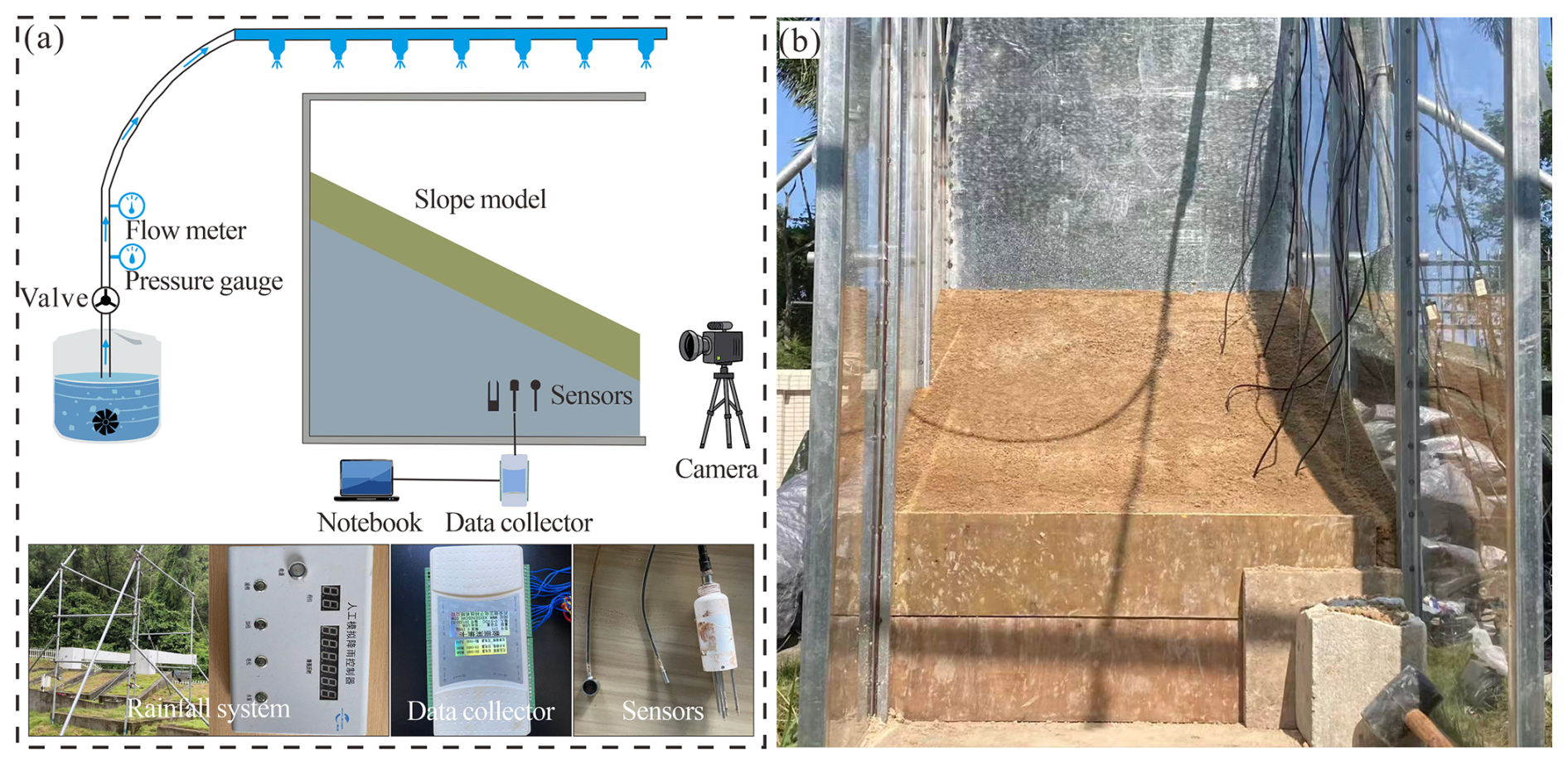
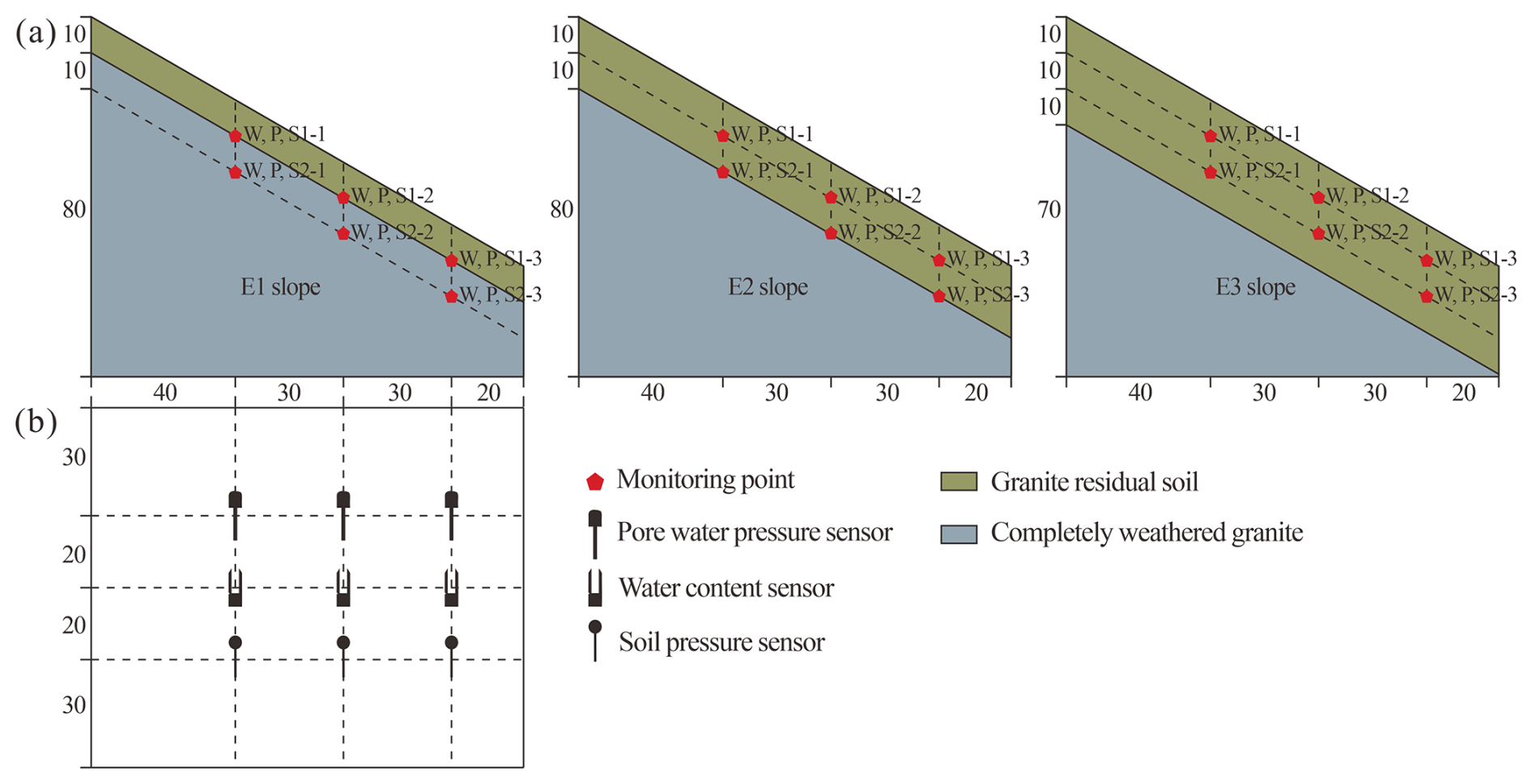
Figure 4Schematic diagram of slope dimension and sensor buried position (unit: cm). (a) Side view. (b) Top view.
Table 2Statistical landslide depth and residual layer thickness.
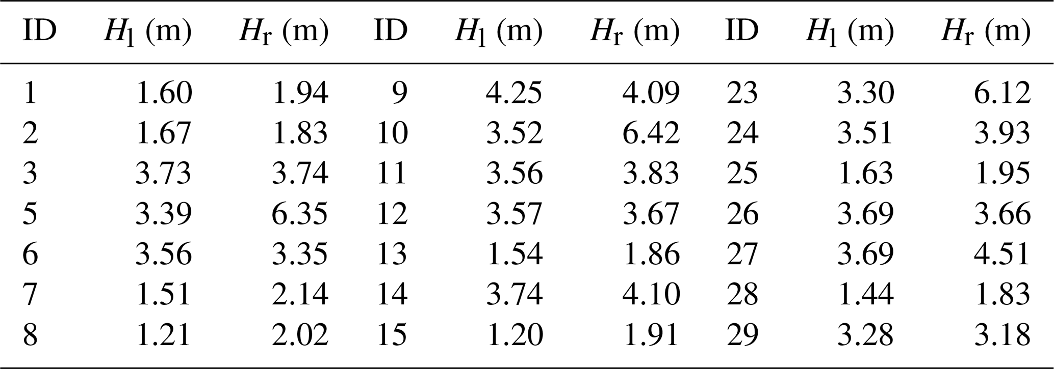
Hl represents landslide depth, Hr represents residual layer thickness.
3.2 Material selection
The selection of experimental materials is the focus of physical model tests. At present, two principal approaches to material selection exist. The first is the use of artificial materials configured based on similarity theory (Zhang et al., 2023; Li et al., 2023). The second is the use of prototypical materials taken directly from the study area (Zhang et al., 2019; Zhen et al., 2023). This test focuses on the impact of performance differences among geotechnical bodies on slope damage, so the selection of prototypical materials can more objectively reflect the rainfall infiltration law and deformation damage process of this type of slope. The test model comprises the residual layer and the weathered layer. Residual soil and completely weathered granite were first sampled in the landslide area and then remodeled indoors based on particle gradation and initial mass moisture content. The specific parameters of the material are shown in Table 1.
3.3 Test procedure
The slopes were modeled using the density control method and the layered filling method. The specific test procedure is as follows:
-
The slopes were filled in one layer per 10 cm. The mass of material needed to lay each layer was calculated using the volume of each modeled layer and the predetermined dry density and water content of the geotechnical body.
-
The weathered layer was filled first. The weighed material was spread evenly inside the model box and tamped to the predetermined height. The model was subsequently cut to the predetermined angle based on the grid lines of the sidewalls of the model box. To simulate the interface between the weathered and residual layers, the surface of the weathered layer was scraped. The aforementioned steps were repeated to complete the filling of the residual layer.
-
When the material was stacked to the depth of the sensor pre-embedding during slope construction, the sensor was inserted and secured, while the data collector was turned on to determine if the readings are abnormal.
-
After completing the modeling, the model was covered with tarpaulin and left to stand for 48 h. This allowed for uniform adjustment of the internal water distribution and stress state of the soil body. The rainfall system was initiated to commence the test. The test was terminated if landslides occurred during rainfall.
4.1 Slope failure characteristics
4.1.1 Slope failure process
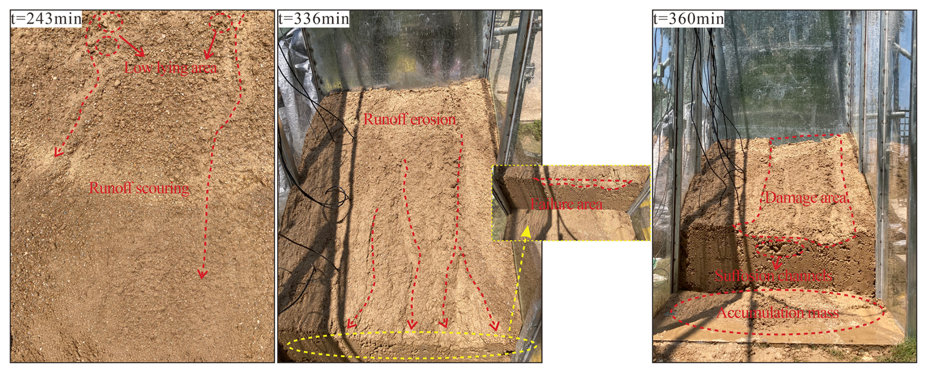
Figure 5 shows the failure process of the E1 slope. As illustrated in the figure, at test 243 min, a small range of low-lying areas was observed on the slope. As rainfall persisted, the residual layer gradually became saturated, and runoff was generated on the slope. The low-lying areas on the slope surface gradually developed into fine gullies as a result of runoff scouring. At test 336 min, the phenomenon of slip collapse was observed at the foot of the slope. The initial fine gullies, subjected to the continuous action of seepage and erosion, ultimately evolved into erosion trenches of a certain depth and width. At test 360 min, extensive damage occurred at the top of the slope, with soil moving with the water flow and eventually accumulating at the foot of the slope. The accumulation mass exhibited looseness, high water content, and mobility. The slope showed an overall flow-slip damage with no obvious sliding surface. The suffosion channels were observed at the foot of the slope.
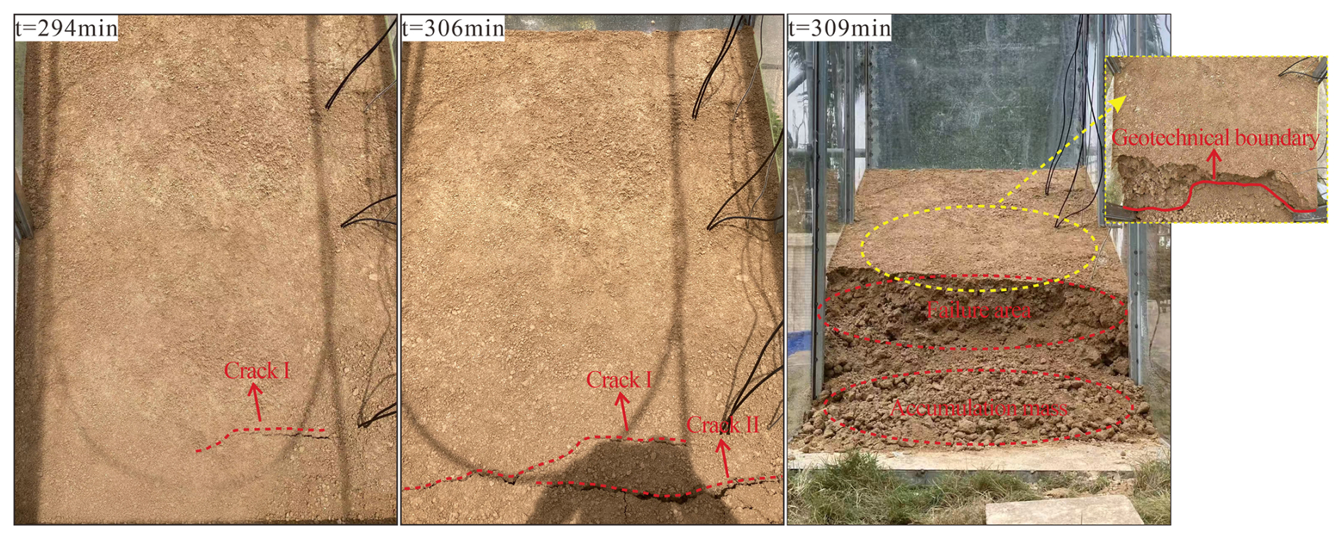
Figure 6 shows the failure process of the E2 slope. As illustrated in the figure, at test 294 min, transverse crack I was observed at the foot of the slope. The formation of the crack is attributed to the continuous flow of rainwater towards the foot of the slope, thereby weakening the soil's resistance to deformation. At test 306 min, the soil body at the foot of the slope exhibited horizontal movement, resulting in uneven settlement of approximately 3 cm of downward misalignment and transverse crack II. Crack II ran almost from the middle to the right border, and crack I had extended to the left border. These two cracks almost traversed the whole slope. At test 309 min, the slope slid along crack I and crack II. The trailing edge of the landslide was located at the foot of the slope, and the sliding surface was positioned at the soil–rock interface. It took only 15 min for the landslide to happen after the appearance of the crack at the foot of the slope. This landslide exhibited sudden sliding characteristics.
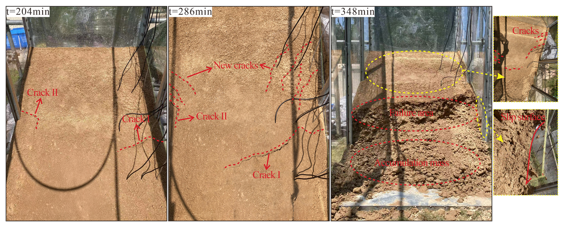
Figure 7 shows the failure process of the E3 slope. As illustrated in the figure, at test 204 min, crack I and crack II were observed at the middle of the slope. These are the tensile cracks caused by uneven settlement of the slope caused by rainfall infiltration. With the infiltration of rainfall, the overall downward deformation of the slope increased, and the slope underwent a shear and tension effect. At test 286 min, crack I was extended and expanded in the lower left direction. New cracks appeared at the top of the slope, arranged in a feathery pattern. At test 348 min, the slope slid along the crack I. The sliding surface exhibited a circular arc shape, and the depth of the landslide was about 23 cm. There were multiple cracks appearing on the slope during the process.
4.1.2 Fine particle migration
In the case of rainfall-induced landslides, it is common for turbid runoff to carry sediment downhill and pile up at the foot of the slope. The phenomenon is essentially particle migration (Lu et al., 2011; Cui et al., 2014). The residual soil lacks intermediate particle size. The coarse particles form the skeleton of the soil, and the fine particles are attached to the skeleton particles as a cement-like substance (Liu et al., 2021). This makes the fine particles able to be carried by water flow and move through the skeleton pore. It is difficult to make direct observations inside the slope without the aid of specialized equipment. In this study, samples were obtained from the top, middle, and foot of the slope of the three groups using a cutting ring. The locations of the samples correspond with the depth of the sliding surface. The fine particles (particle size less than 0.075 mm) in the soil were measured by the particle gradation test, which was then compared with the initial fine particle content. The fine particle content at each location of the slopes at the end of the tests is shown in Fig. 8. It can be seen that there is a large difference in the fine particle content at each location of the E1 slope. The loss of fine particles was most severe at the top of the slope, with a reduction from an initial 39.63 % to 30.61 %. The loss of fine particle content in the middle of the slope was then 7.42 %. Concurrently, the fine particle content at the foot of the slope increased by 8.53 % (Fig. 8a). This indicates that the interior of the slope was undergoing a process of fine particle loss, with the lost portion undergoing longitudinal migration and eventual accumulation at the foot of the slope. The fine particle content of the E2 slope exhibited a 3.18 % decrease at the top of the slope, a 1.16 % decrease at the middle of the slope, and a 2.51 % increase at the foot of the slope (Fig. 8b). The E2 slope has been observed to exhibit a substantial reduction in fine particle loss in comparison to the E1 slope. The fine particle content is nearly identical at all locations in the E3 slope (Fig. 8c). The movement of fine particles in soils of the same type is primarily influenced by in-slope seepage (Wang et al., 2024). It can be seen that seepage is most pronounced on the E1 slope, with no observable seepage on the E3 slope. The loss of fine particles destroys the soil structure, which has a greater impact on slope stability. The gradual increase in pore size between coarse particles within the slope will in turn exacerbate the loss of fine particles, leading to a reduction in the strength of slopes and their susceptibility to damage.
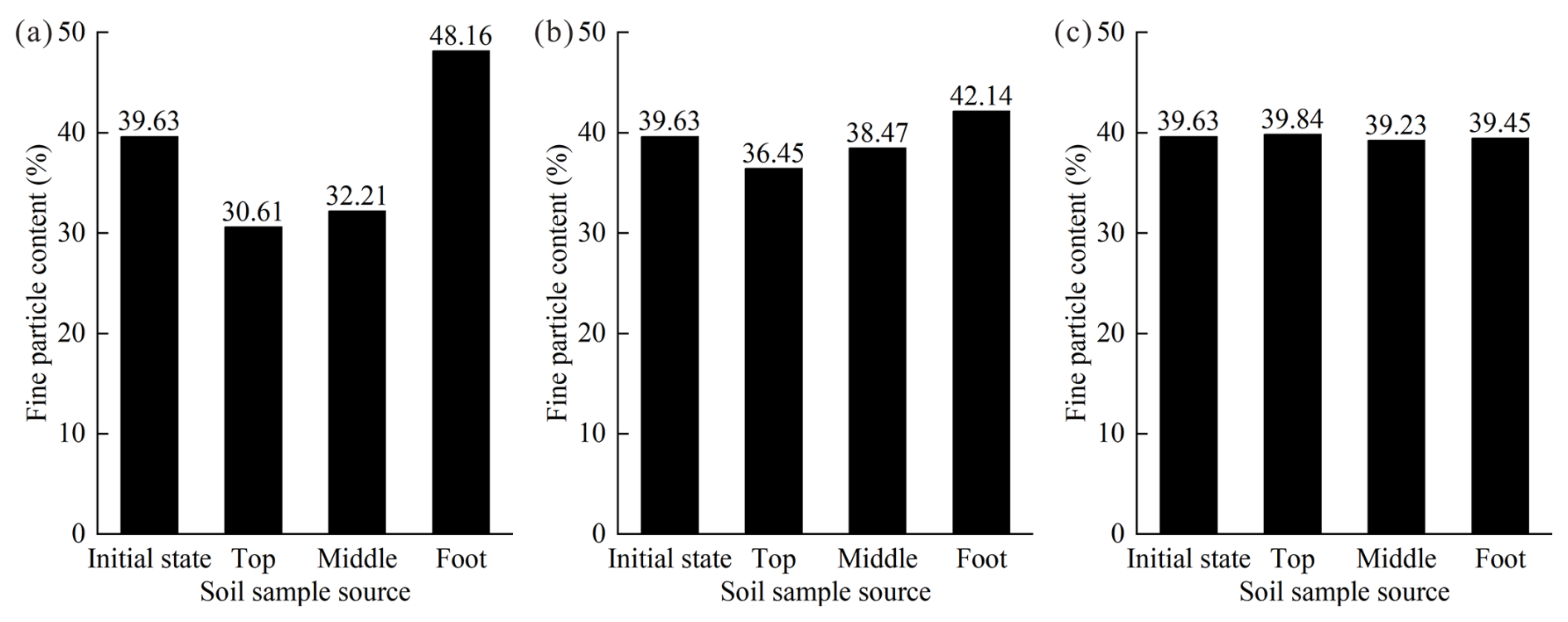
Figure 8Fine particle content at different positions of slopes with different tests. (a) E1 slope. (b) E2 slope. (c) E3 slope.
4.2 Rainfall infiltration process
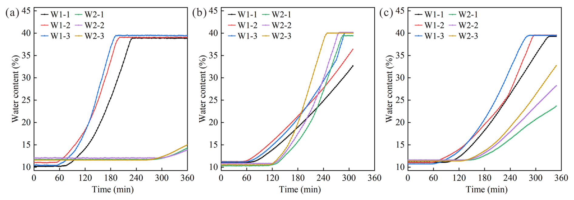
The water content–time curves are presented in Fig. 10. (1) For the E1 slope, at test 57 min, the values of W1-2 and W1-3 increased first, followed by W1-1, indicating that the rainfall had infiltrated to the soil–rock interface and that the water content of the soil near the interface began to increase. Subsequently, the growth rate of W1-1, W1-2, and W1-3 values continued to increase. The values increased sharply and peaked within 135–159 min. This indicates that the soil water content at the soil–rock interface rises rapidly, and the soil becomes saturated in a short period of time. The sensors within the weathered layer did not begin to respond until test 267 min, and the rate of increase in W2-1, W2-2, and W2-3 values was consistently low. At the end of the test, the largest increase in sensor value was only 3.38 %. This suggests that rainfall has a minimal impact on the weathered layer. (2) For the E2 slope, at test 54 min, the values of W1-3, W1-2, and W1-1 commenced an incremental ascent in turn, signifying that the rainfall infiltration had reached 10 cm depth at that moment. At test 111 min, the W2-3 value began to increase, followed by W2-2 and W2-1. This indicates that the rainfall had infiltrated at the soil–rock interface. The values of W2-1, W2-2, and W2-3 increased sharply, and their growth rate was much higher than that of the sensors buried at the 10 cm depth within the slope. The values of W1-1, W1-2, and W1-3 remained stable after 285, 279, and 249 min, respectively. This indicates that the soil at 20 cm depth had reached saturation. At test 273 min, the W1-3 value showed a pronounced increase, suggesting that the rate of soil water content increase at the 10 cm depth at the foot of the slope was considerably more rapid. This is due to the fact that rainwater continues to collect at the slope toe under the influence of seepage within the slope. As the rainfall continued, the soil water content at the foot of the slope eventually became significantly higher than that at the top and middle of the slope, reaching saturation at test 291 min. (3) For the E3 slope, at test 60 min, the infiltration of rainwater into the 10 cm depth resulted in a sequential increase in the values of W1-1, W1-3, and W1-2. At test 138 min, the W2-3 value began to increase, indicating that rainwater infiltrated to the 20 cm depth at the foot of the slope. This was followed by a sequential increase in the values of W2-1 and W2-2. At test 258 min, the W1-2 value showed a significant increasing trend, indicating a swift rise in soil water content at 10 cm depth at the middle of the slope. The reason for this phenomenon is that the crack at the middle of the slope provides easy access for rainfall infiltration, and rainwater infiltrates rapidly in the form of crack-preferential flow. The peak values of W1-3, W1-1, and W1-2 were observed at 288, 303, and 321 min of the test, respectively, indicating that the soil was nearly saturated at 10 cm depth.
The response time of the water content at 10 cm depth was similar for three slopes. This is due to the fact that at the early stage of rainfall, rainwater mainly infiltrated vertically into the shallow surface layer of the slope in the form of homogenous flow. The rate of increase in water content at 10 cm depth was significantly greater on the E1 slope than on the E2 and E3 slopes. The phenomenon is attributed to the infiltration of rainwater into the weathered layer, which has a low permeability. Moisture is prevented from entering the weathered layer due to the effect of capillary force (Wu and Wang, 2025). Besides, the permeability coefficient of the residual soil is an order of magnitude higher than that of the completely weathered granite. It is very easy for violent horizontal seepage to occur at the geotechnical interface with large permeability differences (Wang et al., 2019). Consequently, the rainwater infiltration rate at the soil–rock interface is greatly reduced, resulting in the stagnant water phenomenon. Rainwater tends to flow along the interface. The above phenomenon has also been observed when the rainfall infiltrates to the 20 cm depth within the E2 slope. Notably, the rate of increase in water content was greater at 20 cm depth than at 10 cm depth, which is related to the nature of the residual soil. The residual soil in the study area is weathered from monzonitic granite and contains significant amounts of clay minerals. When saturated with water, clay minerals tend to form a water film of a certain thickness on their surface, thereby reducing the soil permeability (Ma et al., 2025). The rate of rainfall infiltration on the slope will be greatly reduced, resulting in a lower amount of infiltration than discharge. Rainwater accumulates at the soil–rock interface along the penetrating seepage channels, thus forming a temporary water table. The water table gradually rises, and the soil water content in the vicinity of the interface increases at a faster rate than that of soil above the interface. Rainfall on the E3 slope continued to infiltrate downward, and the growth range of sensor values buried at 20 cm depth was slower than that at 10 cm depth. This shows that the rate of water content growth at 20 cm depth was significantly slower than that at 10 cm depth. It is because the transport of infiltrating rainwater to greater depths is affected by the unsaturated permeability of the soil at the wetting front, where the soil is still in the state of initial matrix suction and hinders the vertical downward movement of water (Rahardjo et al., 2005).
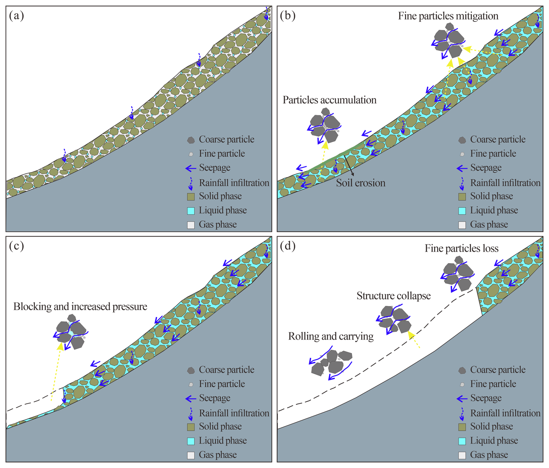
Figure 12Schematic diagram of E1 slope instability. (a) Rainfall infiltration. (b) Runoff and seepage. (c) Local failure. (d) Overall failure.
4.3 Pressure response
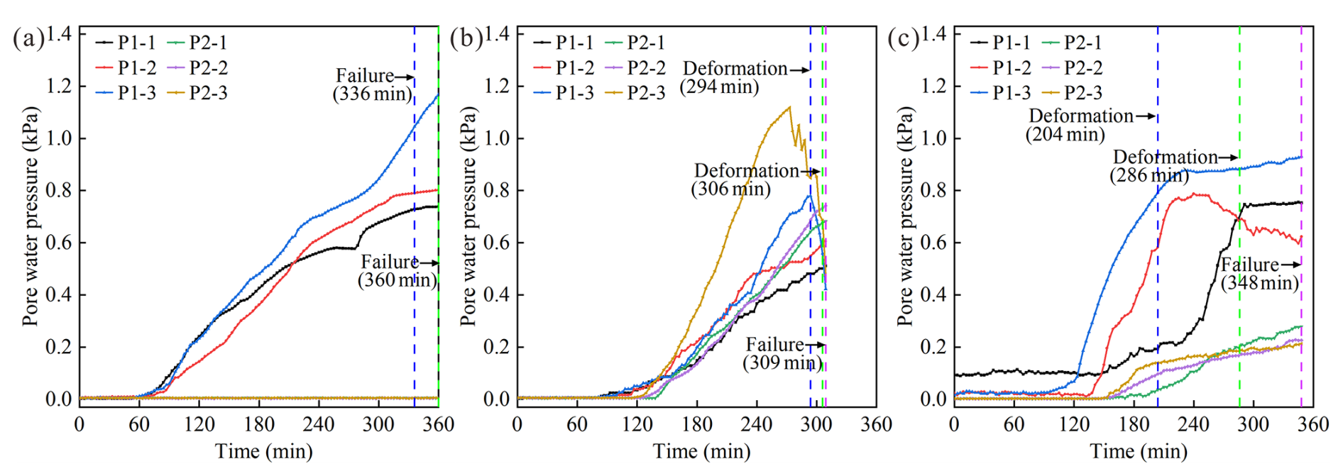
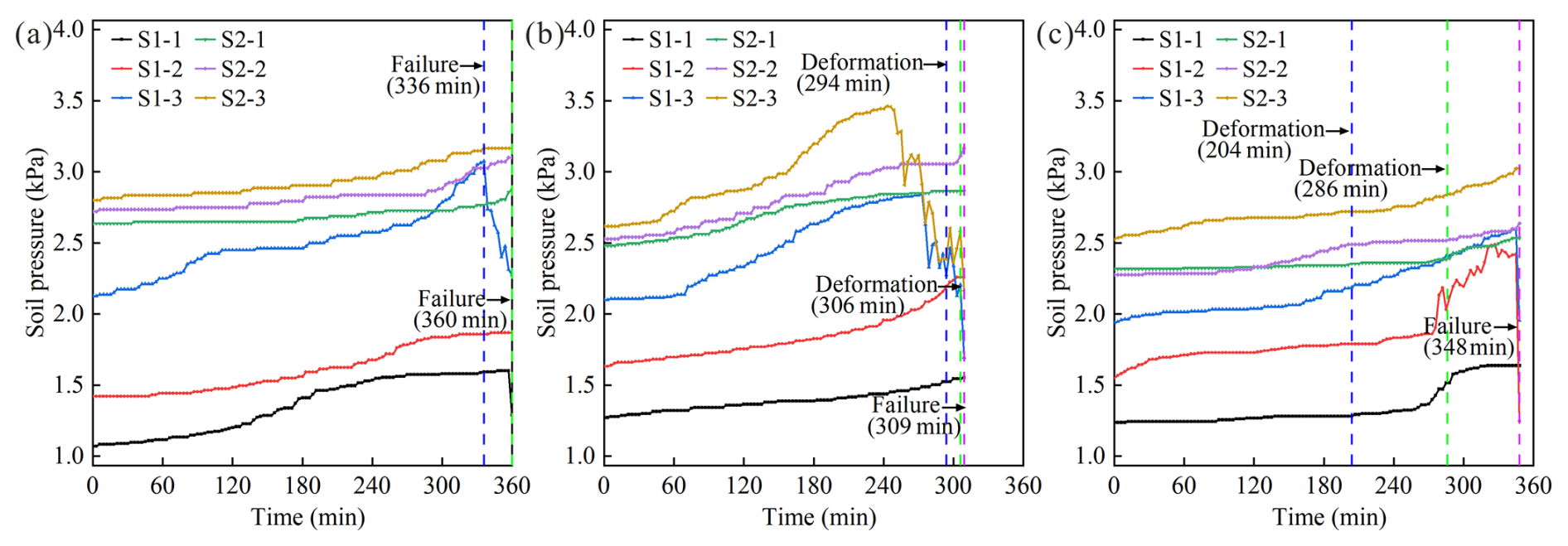
The pore water pressure–time curves are presented in Fig. 10. In general, the pore water pressure change curves exhibit a similar overall trend to the water content change curves. This is due to the fact that the change in pore water pressure is primarily influenced by the soil water content. Furthermore, a partial asynchrony stage has been observed in the changes in pore water pressure and water content, and this has been attributed to the influence of soil deformation on the change in pore water pressure (Iverson et al., 1997). (1) For the E1 slope, the P1-1 value exhibited a slight decline at test 261 min, followed by a rapid increase at test 273 min. This phenomenon may be attributed to the loss of fine particles in soil at the top of the slope, which results in the hollowing out of the soil skeleton, composed of coarse particles. The reclosure of the pore subsequent to the collapse of the skeleton resulted in a sudden increase in pore water pressure. The P1-3 value continued to rise. This is due to the fact that the accumulation of fine particles at the foot of the slope results in pore obstruction, thereby impeding drainage at this location. Consequently, the pore water pressure continues to increase, resulting in damage failure at the foot of the slope. (2) For the E2 slope, the P2-3 value decreased significantly at test 273 min, preceding the deformation observed, indicating that significant deformation damage occurred at 20 cm depth of the foot of the slope first. At test 294 min, the P1-3 decreased significantly, indicating that the crack has developed upwards to 10 cm depth of the foot of the slope. Subsequently, there is a sharp decrease in values of E1-3 and E2-3, indicating that the foot of the slope is approaching instability. (3) For the E3 slope, the P1-2 value continued to increase at test 204 min, when the slope had deformed. This may be due to the fact that granite residual soil in the area exhibits negative dilatancy (Chen et al., 2024). When shear damage occurred on the slope, the pores within the soil became smaller in size; therefore the pore water pressure continued to increase. At test 255 min, the P1-2 value began to decrease, indicating deformation at 10 cm depth at the middle of the slope. The P1-2 curve exhibited frequent fluctuations, with the value first increasing and subsequently decreasing. This is a sign of slow deformation. The creation of cracks within the slope leads to a decrease in pore water pressure, which is then restored by rainfall infiltration, a cycle that is repeated repeatedly.
In this test, the soil pressure sensor probe was placed perpendicular to the soil surface upward. This embedding method can monitor the change in the sliding thrust of the upper rock and soil mass (Nian et al., 2023). Rainfall infiltration increases the slope's self-weight, leading to an increase in the sliding thrust. Therefore, the soil pressure–time curves show an overall increasing trend. (1) For the E1 slope, the largest increase in the S1-3 value indicates that the landslide thrust increases the most at 10 cm depth at the foot of the slope and that the slope is most vulnerable to damage at that location. The S1-3 value continued to decrease after the damage occurred, indicating that the deformation damage at 10 cm depth at the foot of the slope still continued. (2) For the E2 slope, the trend of the soil pressure curve responds to the slope deformation and damage characteristics consistent with the pore water pressure, which will not be repeated here. Notably, the decrease in S2-3 value is greater than that of S1-3, indicating that the sliding thrust at a depth of 20 cm at the foot of the slope decreases more. This suggests that the degree of deformation of the deeper soils at the foot of the slope is greater than that of the shallower soils. (3) For the E3 slope, the S1-2 value increased significantly at test 273 min. This is due to the fact that water starts to fill in the crack, thereby exerting a hydrostatic pressure on the slope that significantly increases the sliding thrust. When the sliding thrust reaches a certain magnitude, a landslide will occur.
5.1 Formation mechanism
Based on the test results and analyses, the instability process of these three types of slopes can be divided into several stages, and these are shown in Figs. 12, 13, and 14.
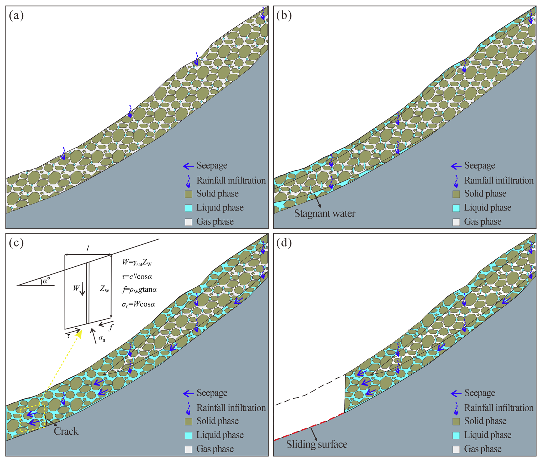
Figure 13Schematic diagram of E2 slope instability. (a) Rainfall infiltration. (b) Stagnant water. (c) Critical sliding. (d) Landslide occurrence.
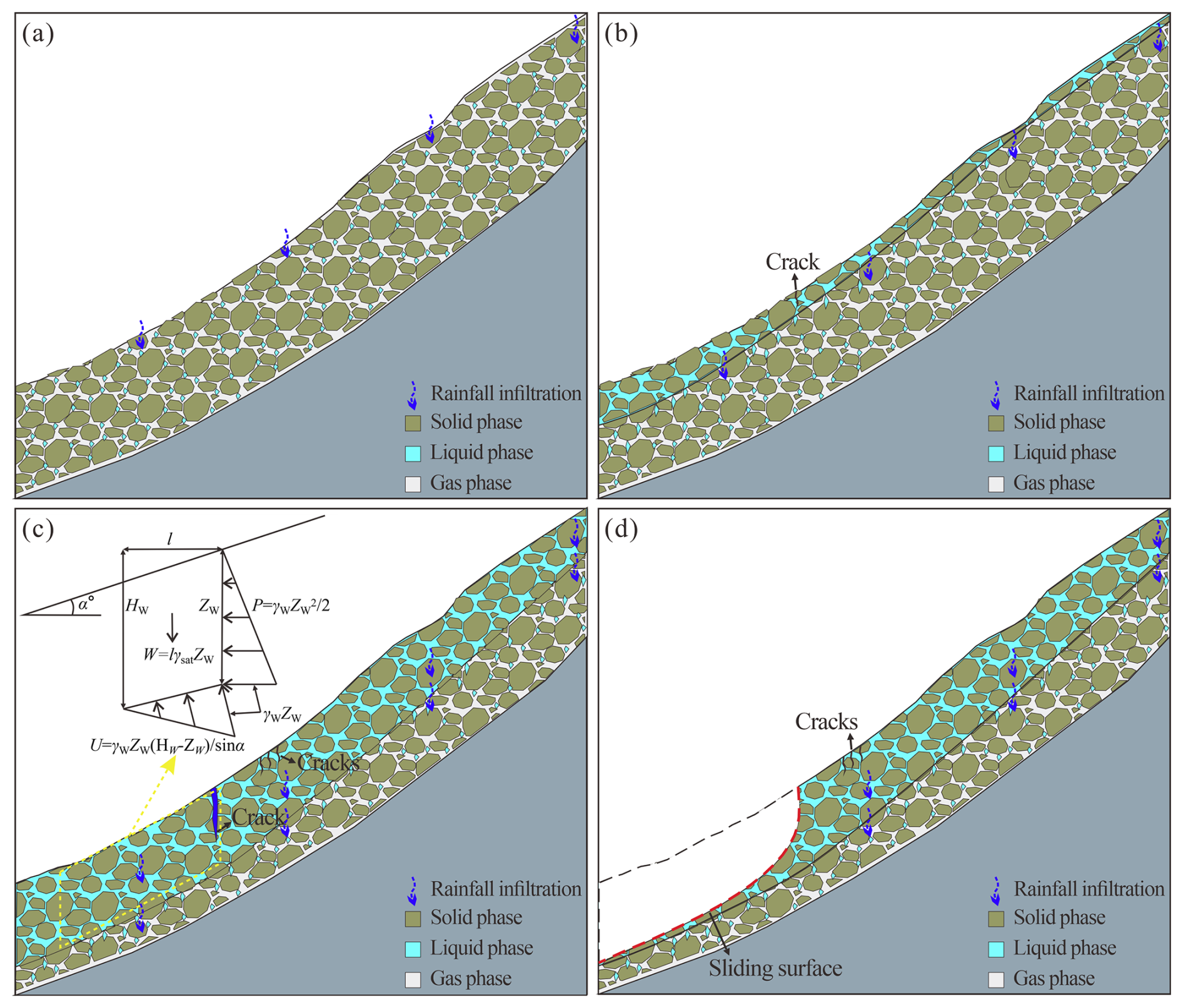
Figure 14Schematic diagram of E3 slope instability. (a) Rainfall infiltration. (b) Crack generation. (c) Critical sliding. (d) Landslide occurrence.
5.1.1 E1 slope
Rainfall infiltration. At the beginning of rainfall, rainfall infiltration into the slope increases the soil water content. There is no evident deformation damage, and surface runoff occurs on the slope.
Runoff and seepage. As rainfall continues, the soil water content of the residual layer gradually increases and reaches saturation. Concurrently, the weathered layer impedes the rainwater infiltration. At this point the rainfall infiltration capacity is reduced, and a proportion of the rainfall is converted into surface runoff. Low-lying areas and gullies are generated by the erosion of surface runoff and splash erosion of rainfall. Erosion damage is most severe at the foot and middle of the slope. Seepage occurs within the residual layer, with the water flow creating seepage force within the soil. Granite residual soil is poorly graded and susceptible to suffosion under seepage. Fine particles in the soil are transported with the water flow and accumulate at the foot of the slope.
Localized failure. As fine particles continue to collect at the foot of the slope, the pores in the soil are blocked. This will make drainage at the foot of the slope difficult, and excess pore water pressure occurs at this location. The effective stress in the soil is lost, leading to a reduction in its resistance to deformation and localized damage at the foot of the slope.
Overall failure. As the soil continues to be subjected to suffosion, the fine particles in the soil are continuously lost. It is difficult for the soil to maintain its structure, and in turn the soil skeleton collapses. Soils with lost structure are prone to disintegration under seepage. At this time, the support at the foot of the slope has been lost, and the soil of the disintegration moves downslope under water flow, showing a wide range of flow-slip failure without an obvious sliding surface.

Figure 15Comparison of Mibei landslide deformation with model tests. (a) E1 slope. (b) E2 slope. (c) E3 slope.
5.1.2 E2 slope
Rainfall infiltration. At the beginning of rainfall, rainfall infiltration into the slope increases the soil water content. There is no evident deformation damage, and surface runoff occurs on the slope.
Stagnant water. As rainfall continues, shallow soil water content gradually increases and becomes saturated, and a saturated zone occurs. When rainfall infiltrates into the soil–rock interface, the underlying weathered layer has weak water permeability, and a relatively impermeable layer is easily formed. Rainwater accumulates at the soil–rock interface, forming a saturated zone. The diffusion rate of this saturated zone is greater than that of the shallow surface layer. The soil is softened at this location, thus forming a plane of weakness.
Critical sliding. Rainwater always flows towards the foot of the slope under gravity, saturating the residual layer at this location. Due to the large difference in permeability between the residual layer and the weathered layer, strong seepage is easily generated along the soil–rock interface. At this time, the sliding mode of the slope is traction and drag, and deformation tends to occur first at the soil–rock interface. Considering the role of hydrodynamic pressure, the calculation formula for the slope stability factor can be expressed as follows:
where α represents slope angle (°), Zw represents saturation zone depth (m), ρw represents water density (kg m−3), γsat represents the water volumetric weight of saturated soil (N m−3), c' represents cohesion of saturated soil (kPa), φ' represents the internal friction angle of saturated soil (°), and g represents gravitational acceleration (m s−2).
Landslide occurrence. When the driving force is greater than the resisting force, the slope generally occurs in a translational slide at the soil–rock interface.
5.1.3 E3 slope
Rainfall infiltration. At the beginning of rainfall, rainfall infiltration into the slope increases the soil water content. There is no evident deformation damage, and surface runoff occurs on the slope.
Crack generation. As rainfall continues, shallow soil water content gradually increases and becomes saturated, and a saturated zone occurs. The increase in water content results in a softening of the soil, thereby reducing its strength. Meanwhile, rainfall infiltration increases the driving force on the slope, causing downward creep. Uneven distribution of soil strength leads to crack generation.
Critical sliding. The crack provides easy access for rainfall infiltration. The accumulation of rainwater within the crack exerts a pressure on the slope, which contributes to the expansion of the cracks. When rainfall is sufficiently adequate, the crack fills with water, creating hydrostatic pressure. At this time, the sliding mode of the slope is characterized by the coexistence of traction and thrust. The source of force that prompts the deformation and damage of the slope mainly comes from the slope's self-weight and hydrostatic pressure. The calculation formula for the slope stability factor can be expressed as follows:
where α represents slope angle (°), l represents horizontal projection of slope length (m), Zw represents height of water level in the crack (m), γw represents water volumetric weight (N m−3), γsat represents water volumetric weight of saturated soil (N m−3), c' represents cohesion of saturated soil (kPa), and φ' represents internal friction angle of saturated soil (°).
Landslide occurrence. When the driving force is greater than the resisting force, the slope occurs generally in a rotational slide within the residual layer.
5.2 Comparison with actual landslides
This study was conducted based on model tests, and the model materials utilized were collected in the field and are considered to be remodeled samples. It should be noted that the constructed slope model may differ somewhat from the actual situation, which may result in limited practical usability of the results of this research. Consequently, this study investigated the correspondence between the actual residual layer thickness and landslides, as well as analyzing the consistency between the findings and the model test results. (1) For the E1 slope, the slopes show clear water flow signs. The water content of the landslide accumulation mass is very high, essentially saturated with water-emitting phenomena. (2) For the E2 slope, the trailing edge of landslides has no cracks other than the transverse tension cracks, which is because the slope deformation starts from a deeper layer. The landslides generate steep free faces due to traction-stagger deformation. (3) For the E3 slope, the number and distribution of tensile cracks at the trailing edge of the landslides are large, which are formed during the downward deformation of the slopes. It is evident that this test accurately replicates the destabilization of granite-weathered crust slopes with different residual layer thicknesses.
5.3 Limitation and prospect
The model tests conducted in this study were subject to the following limitations. Firstly, the selection of the thickness of the residual layer of the slope model was primarily based on the assumption that the thickness of the residual layer exerts an influence on the slope damage pattern. Consequently, the residual layer thickness was not taken into account sufficiently finely. Secondly, the rainfall design of the test was based on actual rainfall scenarios and did not consider the impact of different rainfall characteristics on slope damage patterns, such as the influence of rainfall intensity and rainfall duration. In the next phase of research, tests should be designed to study slope failure patterns under the combined effect of residual layer thickness and rainfall characteristics. This will facilitate the wider application of the research findings.
In this study, physical model tests were designed against the background of clustered landslides in the village of Mibei, Longchuan County, Guangdong Province, China. The hydrological response and damage mechanism of granite-weathered crust landslides with different thicknesses of the residual layers were investigated. Three types of sensors were used to monitor changes in water content, pore water pressure, and sliding thrust at different locations on the slope. The main conclusions are as follows.
Rainfall that infiltrates the soil–rock interface may stagnate due to the difference in permeability coefficients between the residual and weathered layers. Residual soil near the soil–rock interface becomes saturated more rapidly and is prone to seepage along the interface. The thinner the residual layer, the shorter the time for rainfall infiltration to reach the soil–rock interface and the more pronounced the phenomenon of water stagnation and seepage at the interface, which in turn affects the mode and mechanism of slope failure. No evidence of seepage was observed within the slope when the residual layer thickness was 30 cm. In the event of short-term and high-density rainfall, the slope with a residual layer of 10 cm was susceptible to severe suffosion, and overall flow-slip damage occurred without an apparent sliding surface. The slope with a residual layer of 20 cm was prone to traction sliding at the foot of the slope with suddenness, where the sliding surface was at the soil–rock interface. The slope with a residual layer of 30 cm tended to a thrust-type slide at the middle of the slope, where the sliding surface with a circular arc shape was within the residual layer, and the damage process was gradual. The landslides are all cases of shallow damage.
The data used to support the findings of this study are available from the corresponding author upon request.
CJ carried out the artificial model tests, analyzed the test data, and wrote the manuscript. WJ and YS participated in the tests and analyzed part of the data. GQ guided the design and implementation of the tests, as well as revising the content of the manuscript.
The contact author has declared that none of the authors has any competing interests.
Publisher’s note: Copernicus Publications remains neutral with regard to jurisdictional claims made in the text, published maps, institutional affiliations, or any other geographical representation in this paper. While Copernicus Publications makes every effort to include appropriate place names, the final responsibility lies with the authors.
We would like to express our gratitude to the editor and reviewer for their constructive and helpful comments.
This research has been supported by the National Natural Science Foundation of China (grant no. 42271091) and the Natural Science Foundation of Guangdong Province (grant nos. 2024A1515030114 and 2022A1515011898).
This paper was edited by Tom Coulthard and reviewed by Huali Pan.
Bian, S. Q., Chen, G., Meng, X. M., Yang, Y. P., Wu, J., Huang, F. C., Wu, B., Jin, J. C., Qiao, F. Y., Chong, Y., and Cheng, D. L.: Physical model experiment of rainfall-induced instability of a two-layer slope: implications for early warning, Landslides, 21, 3149–3167, https://doi.org/10.1007/s10346-024-02339-0, 2024.
Branco, L. P., Gomes, T. A.,. Cardoso, A. S., and Pereira, C. S.: Natural variability of shear strength in a granite residual soil from porto, Geotech. Geol. Eng., 32, 911–922, https://doi.org/10.1007/s10706-014-9768-1, 2014.
Chen, J. Y., Gong, Q. H., Wang, J., and Yuan, S. X.: Damage cause and mechanism of well-vegetated soil slopes under extreme rainfall: a case study, Front. Earth Sci., 12, 1402798, https://doi.org/10.3389/feart.2024.1402798, 2024.
Chen, Y. B., Gao, Y. F., and Ng, C. W. W.: A new capillary barrier system for retaining wall backfilled with fine-grained soil, Comput. Geotechs., 118, 103324, https://doi.org/10.1016/j.compgeo.2019.103324, 2022.
Cui, P., Guo, C. X., Zhou, J. W., Hao, M. H., and Xu, F. G.: The mechanisms behind shallow failures in slopes comprised of landslide deposits, Eng. Geol., 180, 34–44, https://doi.org/10.1016/j.enggeo.2014.04.009, 2014.
Heidemann, M., Bressani, L. A., and Flores, J. A.: Influence of faults on alteration, mineralogy, and geotechnical behavior of granitic residual soils, Bull. Eng. Geol. Environ., 80, 7051–7068, https://doi.org/10.1007/s10064-021-02351-x, 2021.
Hu, H., Hu, Z., and Ruan, R.: Research on landslide simulated experiment and slope sliding mesoscopic rule of granite residual soil under heavy rainfall, J. Xiamen Univ. (Nat. Sci.), 59, 583–589, https://https://doi.org/10.6043/j.issn.0438-0479.20200403, 2020.
Iverson, R. M., Reid, M. E., and LaHusen, R. G.: Debris-flow mobilization from landslides, Annu. Rev. Earth Planet. Sci., 25, 85–138, https://doi.org/10.1146/annurev.earth.25.1.85, 1997.
Iverson, R. M., Reid, M. E., Iverson, N. R., LaHusen, R. G., Logan, M., Mann, J. E., and Brien, D. L.: Acute sensitivity of landslide rates to initial soil porosity, Science, 290, 513–516, https://doi.org/10.1126/science.290.5491.513, 2000.
Jia, B. Z., Wu, Y. Y., Feng, W. K., Bai, H. L., Xue, Z. H., and Zhao, J. C.: 1# debris flow disaster characteristics and movement process in Mibei Village, Longchuan County, Sci. Tech. Eng., 24, 3576–3585, https://doi.org/10.12404/j.issn.1671-1815.2304262, 2024.
Jiang, Y., Chen, W., Wang, G., Sun, G., and Zhang, F.: Influence of initial dry density and water content on the soil-water characteristic curve and suction stress of a reconstituted loess soil, Bull. Eng. Geol. Environ., 76, 1085–1095, https://doi.org/10.1007/s10064-016-0899-x, 2017.
Krisdani, H., Rahardjo, H., and Leong, E. C.: Application of geosynthetic material in capillary barriers for slope stabilisation, Geosynth. Int., 17, 323–331, https://doi.org/10.1680/gein.2010.17.5.323, 2010.
Li, C. S., Kong, L. W., Shu, R. J., An, R., and Zhang, X. W.: Disintegration characteristics in granite residual soil and their relationship with the collapsing gully in South China, Open Geosci., 12, 1116–1126, https://doi.org/10.1515/geo-2020-0178, 2020.
Li, Y., Xue, K. X., Zhao, Y., Wang, L. L., Bi, J., Wang, T. Y., Wang, S. F., and Zhang, B.: Study on the stability and disaster mechanism of layered soil slopes under heavy rain, Bull. Eng. Geol. Env., 82, 272, https://doi.org/10.1007/s10064-023-03277-2, 2023.
Liao, L. P., Yi, D. M., Tan, Y. H., Ma, S. K., Yang, Y. C., and Liu, Z. W.:Effect of pore air escape and cement dissolution on granite residual soil disintegration, southeast China, Sci. Rep., 15, 10422, https://doi.org/10.1038/s41598-025-92578-5, 2025.
Liu, X. Y., Zhang, X. W., Kong, X. M., and Wang, G.: Effect of cementation on the small-strain stiffness of granite residual soil, Soils Found., 61, 520–532, https://doi.org/10.1016/j.sandf.2021.02.001, 2021.
Lora, M., Camporese, M., Troch, P. A., and Salandin, P.: Rainfall-triggered shallow landslides: infiltration dynamics in a physical hillslope model, Hydrol. Process., 30, 3239–3251, https://doi.org/10.1002/hyp.10829, 2016.
Lourenço, S. D. N., Sassa, K., and Fukuoka, H.: Failure process and hydrologic response of a two layer physical model: implications for rainfall-induced landslides, Geomorphology, 73, 115–130, https://doi.org/10.1016/j.geomorph.2005.06.004, 2006.
Lu, X. B., Ye, T. L., Cui, P., Hu, K. H., and Chen, X. Q.: Numerical investigation on the initiation mechanism of debris-flow under rainfall, J. Mt. Sci., 8, 619–628, https://doi.org/10.1007/s11629-011-2129-0, 2011.
Lu, Y. W., Shi, Y. J., Chen, B., Feng, Z. H., and Hu, J. M.: Structural damage characteristics and mechanism of granite residual soil, Appl. Rheol., 34, 20240011, https://doi.org/10.1515/arh-2024-0011, 2024.
Ma, H., Wang, F. W., Fu, Z. J., Feng, Y. Q., You, Q., and Li, S.: Characterizing the clustered landslides triggered by extreme rainfall during the 2024 typhoon Gaemi in Zixing City, Hunan Province, China, https://doi.org/10.1007/s10346-025-02510-1, 2025.
McKenna, J. P., Santi, P. M., Amblard, X., and Negri, J.: Effects of soil-engineering properties on the failure mode of shallow landslides, Landslides, 9, 215–228, https://doi.org/10.1007/s10346-011-0295-3, 2011.
Monkul, M. M. and Yamamuro, J. A.: Influence of silt size and content on liquefaction behavior of sands, Can. Geotech. J., 48, 931–942, https://doi.org/10.1139/t11-001, 2011.
Monkul, M. M., Etminan, E., and Senol, A.: Influence of coefficient ofuniformity and base sandgradation on static liquefaction of loose sands with silt, Soil Dyn. Earthq. Eng., 89, 185–197, https://doi.org/10.1016/j.soildyn.2016.08.001, 2016.
Ng, C. W. W., Qu, C. X.,Cheung, R. W. M., Guo, H. W., Ni, J. J., Chen, Y. B., and Zhang, S.: Risk assessment of soil slope failure considering copula-based rotated anisotropy random fields, Comput. Geotechs., 136, 104252, https://doi.org/10.1016/j.compgeo.2021.104252, 2021.
Nian, G. Q., Chen, Z. H., Zhu, T. Y., Zhang, L. F., and Zhou, Z. H.: Experimental study on the failure of fractured rock slopes with anti-dip and strong weathering characteristics under rainfall conditions, Landslides, 21, 165–182, https://doi.org/10.1007/s10346-023-02142-3, 2023.
Qi, X., Li, Q. H., Jiao, Y. Y., and Tan, F.: Vertical zoning criteria and engineering geological characteristics of super-thick layer granite weathering crust in Wuzhou City, J. Eng. Geol., 30, 407–416, https://doi.org/10.13544/j.cnki.jeg.2020-159, 2022.
Rahardjo, H., Lee, T. T., Leong, E. C., and Rezaur, R. B.: Response of a residual soil slope to rainfall, Can. Geotech. J., 42, 340–351, https://doi.org/10.1139/t04-101, 2005.
Rahardjo, H., Santoso, V. A., Leong, E. C., Ng, Y. S., and Hua, C. J.: Performance of an instrumented slope covered by a capillary barrier system, J. Geotech. Geoenviron., 138, 481–490, https://doi.org/10.1061/(asce)gt.1943-5606.0000600, 2012.
Su, S. X. and Zhang, Y. X.: Similarity criterion in physical simulation of rainfall and sheet flow, T. Chin. Soc. Agric. Eng., 28, 93–98, https://doi.org/10.3969/j.issn.1002-6819.2012.11.016, 2012.
Wang, B. L., Wang, Q. W., Li, Y., Yao, Z. G., and Wang, H. F.: Flume experiments to study fine-grain migration and its impact on slope stability, J. Mt. Sci., 21, 3552–3566, https://doi.org/10.1007/s11629-024-8833-3, 2024.
Wang, D. Y., Zeng, J., Wang, J., and Zhou, M.: Effect of dry-wet cycle on stability of granite residual soil slope, IOP Conference Series: Earth Env. Sci., 526, 12046, https://doi.org/10.1088/1755-1315/526/1/012046, 2020.
Wang, J., Gong, Q. H., Yuan, S. X., and Chen, J.: Combining soil macropore flow with formation mechanism to the development of shallow landslide warning threshold in South China, Front. Earth Sci., 10, 1048427, https://doi.org/10.3389/feart.2022.1048427, 2023.
Wang, S. H., He, J., and Liu, H.: Mechanism of water flow migration evolution in multi-layer soil slope during rainfall infiltration, J. Northeast. Univ. (Nat. Sci.), 40, 1172–1177, https://doi.org/10.12068/j.issn.1005-3026.2019.08.020, 2019.
Wu, L. Z., Huang, R. Q., Li, H. L., Li, X., and Sun, P.: The model tests of rainfall infiltration in two-layer unsaturated soil slopes, Eur. J. Environ. Civ. En., 25, 1555–1569, https://doi.org/10.1080/19648189.2019.1585961, 2019.
Wu, Q. H. and Wang, K.: Effect of angle and lithology on infiltrating to fine/coarse dual-structure slope under rainfall condition, Earth Sci., 50, 311–321, https://doi.org/10.3799/dqkx.2023.170, 2025.
Wu, S., Zhao, R., Liao, L., Yang, Y., Wei, Y., and Wei, W.: Failure mode of rainfall-induced landslide of granite residual soil, southeastern Guangxi Province, China, Earth Surf. Dynam., 10, 1079–1096, https://doi.org/10.5194/esurf-10-1079-2022, 2022.
Xu, X. T., Jian, W. B., Wu, N. S., and Xu, X.: Model test of rainfall-induced residual soil slope failure, China J. Highw. Transp., 31, 270–279, https://doi.org/10.19721/j.cnki.1001-7372.2018.02.029, 2018.
Yang, G. L., Zhao, L. H., Qin, Y. G., Yang, T., and Chen, S.:Clustered landslides induced by rainfall in Jiangwan Town, Shaoguan City, Guangdong Province, China, Landslides, https://doi.org/10.1007/s10346-025-02463-5, 2024.
Zhang, B. C., Ning, Y. B., Tang, H. M., Ding, B. D., Fang, K., and Zou, Z. X.: Study on the evolutionary process of interbedded anti-inclined slope block-flexure toppling in the upper Yalong River, Bull. Eng. Geol. Env., 82, 240, https://doi.org/10.1007/s10064-023-03223-2, 2023.
Zhang, S., Zhang, X. C., Pei, X. J., Wang, S. Y., Huang, R. Q., Xu, Q., and Wang, Z. L.: Model test study on the hydrological mechanisms and early warning thresholds for loess fill slope failure induced by rainfall, Eng. Geol., 258, 105135, https://doi.org/10.1016/j.enggeo.2019.05.012, 2019.
Zhang, W., Ali, M. Z., Cui, W. F., Sun, C. G., Zheng Z. W., and Chen, K. J.: Severe rainfall-induced landslides in Pingyuan County, Guangdong, China, in June 2024, Landslides, https://doi.org/10.1007/s10346-025-02546-3, 2025.
Zhang, Y. Y.: Eroding soil types and their management counter measures of granite regions in Guangdong Province, China, J. Mt. Sci., 27, 49–53, https://doi.org/10.16089/j.cnki.1008-2786.2009.01.003, 2009.
Zhen, J., Yang, X. J., Wang, B. Z., Fan, H. H., and Meng, M. Q.: Study on the destruction of backfilled loess slopes by short-term extreme rainfall erosion, Bull. Eng. Geol. Env., 82, 406, https://doi.org/10.1007/s10064-023-03426-7, 2023.