the Creative Commons Attribution 4.0 License.
the Creative Commons Attribution 4.0 License.
 | 22 Jul 2022
Linking levee-building processes with channel avulsion: geomorphic analysis for assessing avulsion frequency and channel reoccupation
Jeongyeon Han
A natural levee is a typical wedge-shaped deposit adjacent to a river channel. Given its location and distinctive features, the levee can serve as a key to revealing depositional processes of the coupled channel to floodplain system preserved in the rock record. Levee–floodplain topographic evolution is also closely linked to river avulsion processes which can cause catastrophic floods. Nonetheless, the levee geometry and its aggradation pattern on the floodplain have not been fully incorporated in the study of avulsion. Here, we present a levee-building model using advection settling of suspended sediment to reproduce the evolution of a fluvial levee over floods and to examine the effects of boundary conditions on levee geometry and the grain-size trend of the levee deposit. We further investigate river avulsion frequencies and potential channel reoccupation associated with the grain-size distribution of overbank sediment flux and the overflow velocity into the floodplain, both of which can control the levee geometry, especially the aggradation rate at the levee crest. In the modeling results, the levee develops (1) a concave-up profile, (2) an exponential decrease in grain size of the deposit away from the main channel, and (3) a relatively steeper shape for coarser sediment supply and vice versa. The subsequent scaling analysis supports that the input grain size to the floodplain and levee profile slope are positively correlated with the avulsion frequency, whereas the overflow velocity is inversely proportional to the avulsion frequency. In connection with the avulsion styles and levee geometry, we suggest that relatively steeper levee slopes tend to promote more reoccupations of preexisting floodplain channels as protecting abandoned channels from topographic healing, but relatively gentler levees are likely to create a new avulsion channel as their remnant channels are more vulnerable to the removal of topographic memory. The insights drawn from the current modeling work may thus have potential implications for reconstructing paleoenvironments in regard to river sediment transport and flood dynamics via levee deposits. Based on the roles of natural levees on the avulsion frequency and channel reoccupation, the flood hazards triggered by river avulsions as well as the alluvial architecture in sedimentary records can be better assessed.
- Article
(4691 KB) - Full-text XML
-
Supplement
(612 KB) - BibTeX
- EndNote


During floods, rivers overflow into floodplains, facilitating the deposition of suspended sediment due to the loss of flow competence and transport capacity. The reductions in competence and capacity are responsible for the decreases in depositional rate and grain size of sediment away from the rivers and form distinctive wedge-shaped natural levees along the channel margins. Because of their unique location at the boundary, levees may represent an important linkage between the mainstream and overbank processes (Allen, 1965; Brierley et al., 1997; Wolman and Leopold, 1957). According to Brierley et al. (1997), this linkage between the channel and floodplain facies could further play a critical role in assessing river types that cover the geometry, size, and distribution of the channel deposits in stratigraphic records.
Despite the geomorphologic and stratigraphic importance of levee deposits, there have been a limited number of publications on fluvial levee depositional processes. Indeed, a few early numerical models of overbank suspended sediment transport and depositional processes have been carried out. These models include James (1985) and Pizzuto (1987), which have been a great aid in comprehending the mechanisms of overbank configuration (e.g., floodplain topography) by quantifying the depositional patterns of suspended sediment and grain-size distribution across the channel margin to the floodplain. Similarly, some studies have probed the detailed evolution of levee geometry based on the field investigations of natural levees (Adams et al., 2004; Cazanacli and Smith, 1998; Ferguson and Brierley, 1999; Filgueira-Rivera et al., 2007; Gugliotta et al., 2018; Johnston et al., 2019; Pierik et al., 2017; Skolasiñska, 2014; Smith and Pérez-Arlucea, 2008). Cazanacli and Smith (1998) described the geometry and lateral grain-size distributions of fluvial levees, where the differences in levee shape and slope are attributed to non-uniform deposition of coarse overbank sediment. Ferguson and Brierley (1999) stated that the stream power determined by valley width is essential for levee accretion and floodplain stripping, and thus the preservation potential of levee deposits. Recent work by Pierik et al. (2017) found that the dimensions of levees and their changes in time are associated with both environmental forcing (e.g., suspended sediment influx and flood intensity) and initial geomorphic conditions (e.g., flood basin configurations). Even with the earlier findings, there is still a need to ascertain the primary driver of levee geomorphology to accurately delineate and interpret field data of modern river systems and ancient fluvial records.
Moreover, there have been no attempts to establish a fluvial levee-building model accounting for the river avulsion processes by measuring depositional patterns of levee deposits, which would be also an important step forward to understanding the influence of natural levees in connecting in-channel and floodplain evolution. River avulsion, an abrupt relocation of a river from an established channel to a fresh or formerly abandoned channel, is one of the important processes for river dynamics and fluvial stratigraphy. It has long been known that the channel perching, in which the flow potential energy would increase as a result of the in-channel bed and levee crest aggradations, leads to lateral instability and consequently channel avulsion (Bryant et al., 1995; Imran et al., 1998; Mohrig et al., 2000). After multiple floods, levee deposits can simultaneously be accumulated as much as the in-channel deposits and serve as a local superelevation, the relief between levee crest and minimum low point of the nearby floodplain (Bryant et al., 1995; Heller and Paola, 1996; Mohrig et al., 2000). The study by Mohrig et al. (2000) suggested that comparing channel depth with levee crest height (i.e., normalized superelevation) can be regarded as an avulsion criterion. It is traditionally thought that the river would avulse when the levee crest height reaches approximately one channel depth. The aggradation rates of both local superelevation and in-channel bed can be governed by the water and sediment supplies in the main channel and overbank flows, changes in flood regime, and other factors including cohesion and vegetation type, which in turn impact the temporal and spatial patterns of avulsions (Chadwick et al., 2020; Ganti et al., 2016; Mohrig et al., 2000; Stouthamer and Berendsen, 2001; Tooth et al., 2007). Some researchers have recently proved that even climate change and anthropogenic effects such as land use and deforestation, can enforce dramatic changes in channel avulsion behaviors and increase the possibilities of catastrophic flooding disasters in densely populated communities near river systems (Chadwick et al., 2020; Mishra and Sinha, 2020; Pearce, 2021; Slingerland and Smith, 2004). Yet, the understanding of river avulsion associated with floodplain architecture, especially with levee morphology is still insufficient. With these concerns in mind, it would be a great task to unravel the relationship between river switching and levee-building processes linked to the flood conditions for predicting modern avulsion processes and diminishing the threats posed by avulsion flooding events (Hajek and Wolinsky, 2012; Valenza et al., 2020).
In this study, we develop an advection-settling, suspended sediment transport model to quantitatively determine what are the main controls on the geometry, depositional rate, and grain-size sorting in fluvial levee evolution during flooding. In particular, previous studies of levee formations (e.g., Cazanacli and Smith, 1998; Filgueira-Rivera et al., 2007; Hudson and Heitmuller, 2003) highlighted that levee morphology is determined by flood-basin dynamics, such as overflow hydraulics, the grain-size distribution of suspended sediment, and the maximum channel water stage. Therefore, to investigate the flood-basin dynamics under simplified conditions, a total of five tests are designed in which the overflow velocity, grain size, entrainment, and the flood level condition are varied. We then explore river avulsion frequencies and channel reoccupation associated with the levees constructed differently under the various input sediment grain sizes and flood-flow discharges and demonstrate the contributions of levee deposits to the mechanisms governing the river avulsion behaviors. Lastly, we address the implications of our findings to modern river systems and fluvial rock records.
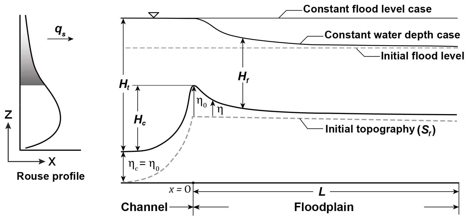
Figure 1Schematic of a levee with the Rouse profile used in the model. The extent of suspended sediment supplied to the floodplain (qs) is gray colored on the Rouse profile. Note that the upstream end of the model is assigned at the channel-floodplain boundary as the origin (x=0) where the levee crest develops and the downstream direction of the model is towards the distal floodplain, to which x increases.
2.1 1D levee building model
Consider an initially flat floodplain adjacent to a flooded channel, the overflow carries suspended sediment from the channel to the floodplain, and the suspended sediment settles to build a levee (Han and Kim, 2022a, b) (Fig. 1). The mass conservation of suspended sediment takes the following form:
where Hf is the depth of overflow in the floodplain, the subscript i represents the ith grain-size range, denotes the average suspended sediment concentration (SSC) in the flood flow, qs denotes the volume transport of suspended sediment per unit width, and Es and Ds are the entrainment and deposition rates per unit width, respectively. This governing equation calculates the change in SSC for each grain-size range with time.
The total sediment flux at the channel–floodplain boundary (at the boundary between the channel margin and the floodplain), qso depends on the distribution of SSC in the channel. We use the Rouse equation (Rouse, 1937) to illustrate the vertical sediment concentration profile in the channel and integrate the concentration profile to produce qso only over the depth between the levee crest and water surface (Fig. 1). The Rouse equation is written as:
where is the sediment concentration for the ith grain-size range at elevation z, denotes the near bed concentration at z=a, and Ht is the total flow depth. In this model, we adopt a reference near bed height as a=0.05Ht, proposed in Garcia and Parker (1991) and assume the grain-size distribution of suspended sediment to be normally distributed with a standard deviation of σ=0.8. The Rouse profile in the channel depends on the total sediment flux of the channel (qts) and the near bed concentration (), and both are kept constant with time considered as simplified stead flow (Pizzuto, 1987). Pi denotes the dimensionless Rouse number for the ith grain-size range in which wsi denotes the settling velocity, κ is the von Karman constant of 0.41, and u* is the shear velocity. We apply the settling velocity (wsi) equation as in Ferguson and Church (2004) where the grain-shape constants are C1=18 and C2=1 for natural grains; R is submerged specific gravity; g is gravitational acceleration; di is the ith grain-size range; and ν is the kinematic viscosity of fluid.
We make an erodible substrate at the beginning, supposing suspended sediment in the initial flood flow to be uniformly mixed and settled over the entire floodplain instantaneously (i.e., the time for levee deposition is much longer than that for the flood inundation over the floodplain). The initial concentration of suspended sediment in the floodplain can be defined as:
where α denotes a constant (α=0 for fresh flood water and α>0 for an initial sediment concentration) which we set at α=1 for simplicity. Uf and Hf denote the initial flow velocity and depth in the floodplain, respectively.
The depositional rate for the ith grain-size range Dsi is described as a function of settling velocity and the concentration of suspended sediment:
in which is the near bed concentration in the floodplain. The near bed concentration of floodplain is defined as where β is a dimensionless factor and assumed unity for simplicity.
For the entrainment rate of the ith grain-size range Esi, the relations of Garcia and Parker (1991) for non-uniform sediment are employed. The relations can be expressed as:
where Eui is the dimensionless entrainment rate of the ith grain-size range per unit area, Fi denotes the ith grain-size fraction entrained from the bed, and A is a constant set at . According to Garcia and Parker (1991), the similarity variable for the ith grain-size range, Zui can be written as:
where is Reynold's particle number for the ith grain-size range; , where σ denotes the arithmetic standard deviation of the surface sediment in the grain-size scale ψ; u*s is the shear velocity associated with skin friction; and d50 is the median grain size on the sediment surface.
Combining the governing equation, Eq. (1) with the Exner equation of conservation of bed sediment yields the following form for the time evolution of the bed elevation η[x,t] as:
This indicates that the topographic elevation is a product of a balance between the entrainment and settling of suspended sediment. The study assumes that all suspended sediment in the floodplain is deposited with no porosity (λp=0) for simplicity. We note that these simplifying assumptions can be relaxed in a future, in a more elaborate model.
2.2 Test parameters
In order to test our numerical model, we apply approximate field-scale parameters based on previous studies in the Vistula River at the Smolice station, southern Poland (Pruszak et al., 2005; Wyżga, 1999). The dimensions and flow properties of the channel and floodplain have been chosen based on the field observations of flow hydraulics and natural levee deposits in the Vistula River (Wyżga, 1999). A constant overflow depth in the floodplain (Hf) of 4 m was employed with a channel depth (Hc) of 4 m. The flow velocity (Uc) in the channel and overflow velocity in the floodplain (Uf) were kept at constant values of 1.5 and 0.1 m s−1, respectively. We set a cross-valley slope (cf. Mackey and Bridge, 1995) as an initial floodplain (cross-valley) slope (Sf) which is tilted into the distal floodplain, and the slopes of the channel and floodplain in the model were assigned the same as .
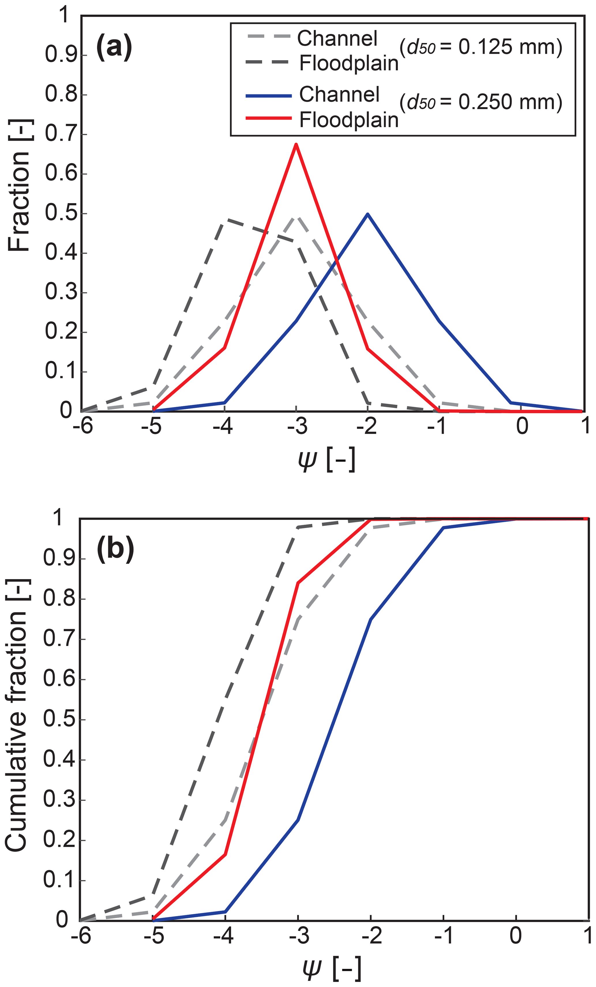
Figure 2(a) Grain-size distribution curves and (b) cumulative grain-size distributions of suspended sediments at near bed and at channel-floodplain boundary. Dashed lines are for the channel (gray) and floodplain (black) when d50=0.125 mm and solid lines are for the channel (blue) and floodplain (red) when d50=0.250 mm, respectively.
Table 1Initial boundary conditions for the 5 Test runs.
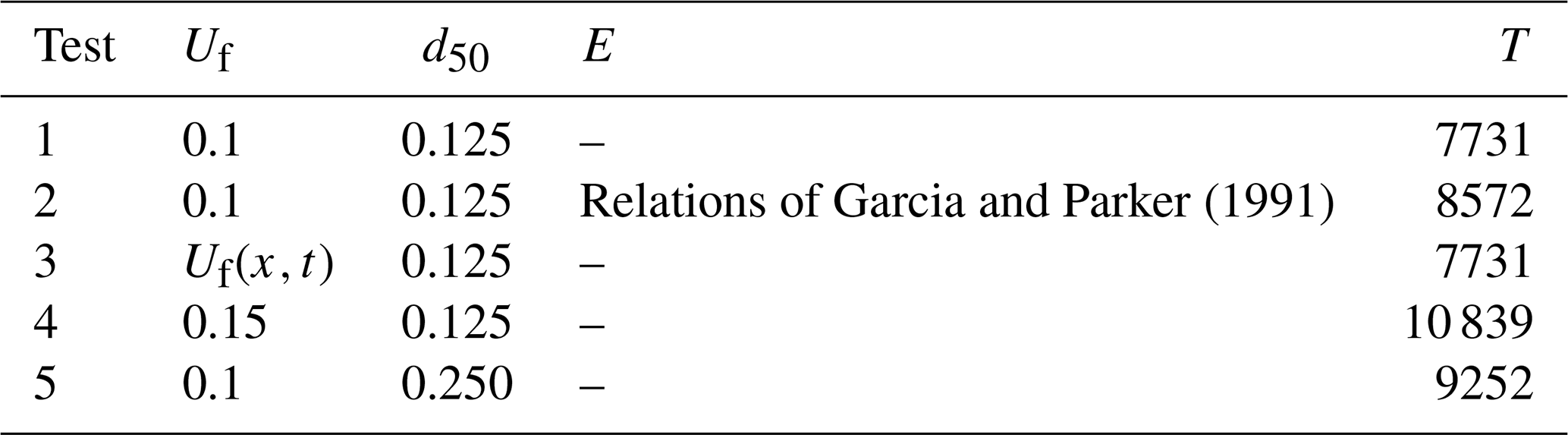
Uf=Q flow velocity on floodplain [m s−1]. d50 = median grain size of suspended sediment in channel [mm]. T = simulation time [min]. E = entrainment [–].
Derived from Eqs. (2) and (3), we integrated suspended sediment concentrations in the channel for each grain size above the floodplain elevation, which are used for defining an overbank sediment flux at the channel–floodplain boundary, qso. It is assumed that the elevations of the main channel bed and levee crest increase at the same aggradation rate (Filgueira-Rivera et al., 2007; Jobe et al., 2020), so that input SSC entering the floodplain remains constant in the model (Fig. 1). We approximate the total suspended sediment flux in the channel (qts) of 0.001 m2 s−1 by the equation from Guy (1970) presuming a total SSC in the channel of 0.034 kg m−3 obtained from Pruszak et al. (2005). We also allocate SSCs for seven different grain sizes at the channel near bed with the median grain size (d50) of 0.125 mm estimated from Wyżga (1999). Figure 2 shows the grain-size distribution of suspended sediment both for the near-bed channel and for the floodplain supplied at the channel-floodplain boundary. The fractions of each grain size and the cumulative distributions are represented in Fig. 2a and b, respectively. We observe in both figures, that the incoming sediments to the floodplain are finer than SSC in the channel because only the suspended sediments above the levee crest elevation are taken to transport to the floodplain. The initial 200 m over the floodplain (L) from the channel-floodplain boundary is divided into 20 grid nodes (N) in the model and each node stores modeling results of topographic elevation, grain size, and SSC to analyze their spatial and temporal trends from the proximal to distal locations. Suspended sediment reaching over the floodplain width (L>200 m, here) would leave through the downstream boundary of the model domain.
2.3 Test setup
The main purpose of our test model is to gain a first-order understanding of the fluvial levee evolution under various but simple boundary conditions. We focused on changes in the levee profile associated with the overbank flow velocity and the median grain size of suspended sediments. We also dealt with the effects of entrainment and flood water level on the levee evolution and stratigraphic development in our model. All these parameters are summarized in Table 1. A total of 5 tests were performed until the levee crest in each run (at the channel-floodplain boundary) reaches a height of 2 m. The total simulation times (T) were different in the runs in response to various depositional rates at the levee crest calculated with the varied boundary conditions. Based on the adapted parameters from a field example, we set a prototype model as Test 1. To estimate the entrainment effect, Test 2 contained the entrainment relations of Garcia and Parker (1991) in Eqs. (6) and (7) whilst the other tests assume no entrainment. The case of constant water depth in the prototype model was compared to the constant flood level case in Test 3 (Fig. 1). Test 4 was simulated with 1.5 times higher flood flow velocity than that in Test 1. We doubled the median grain size (d50) of SSC at the channel near bed from 0.125 mm in Test 1 to 0.25 mm in Test 5. Figure 2 depicts the grain-size distributions of Tests 1 and 5 at the channel and the floodplain. The model produced levees in the cross-sectional view and could predict the proximal to distal grain-size distribution in the levee deposits. The final surface profiles and the time series of surface elevation changes at the proximal (grid node N=3) and distal (grid node N=15) locations were captured. We then plotted the grain-size fining trends in the distal direction and the grain-size changes over time at the proximal and distal locations. All modeling results are shown against the results from the prototype model (Test 1) to identify the differences.
3.1 Levee profile
The cross-sectional views of predicted levee topography are presented in Fig. 3. The dashed black and solid red lines are the results of the prototype model (Test 1) and other test runs, respectively. The elevation of Test 2 at the proximal distance near the levee crest was slightly lower than Test 1, whereas, at the distal locations, Test 2 has slightly higher elevations (Fig. 3a). However, the differences (caused by the entrainment) are quite subtle. In Fig. 3b, the results do not indicate any noticeable differences between Tests 1 and 3 with the different flood level conditions. The total simulation times for both two models are also the same (Table 1). The levee profile of Test 4 using a higher flood velocity, shown in Fig. 3c, is gentler in slope and takes a longer time to build up the levee crest of 2 m in height. Test 5 with an increase in grain size produces a steeper slope of levee despite the longer total run time compared with Test 1 (Fig. 3d).
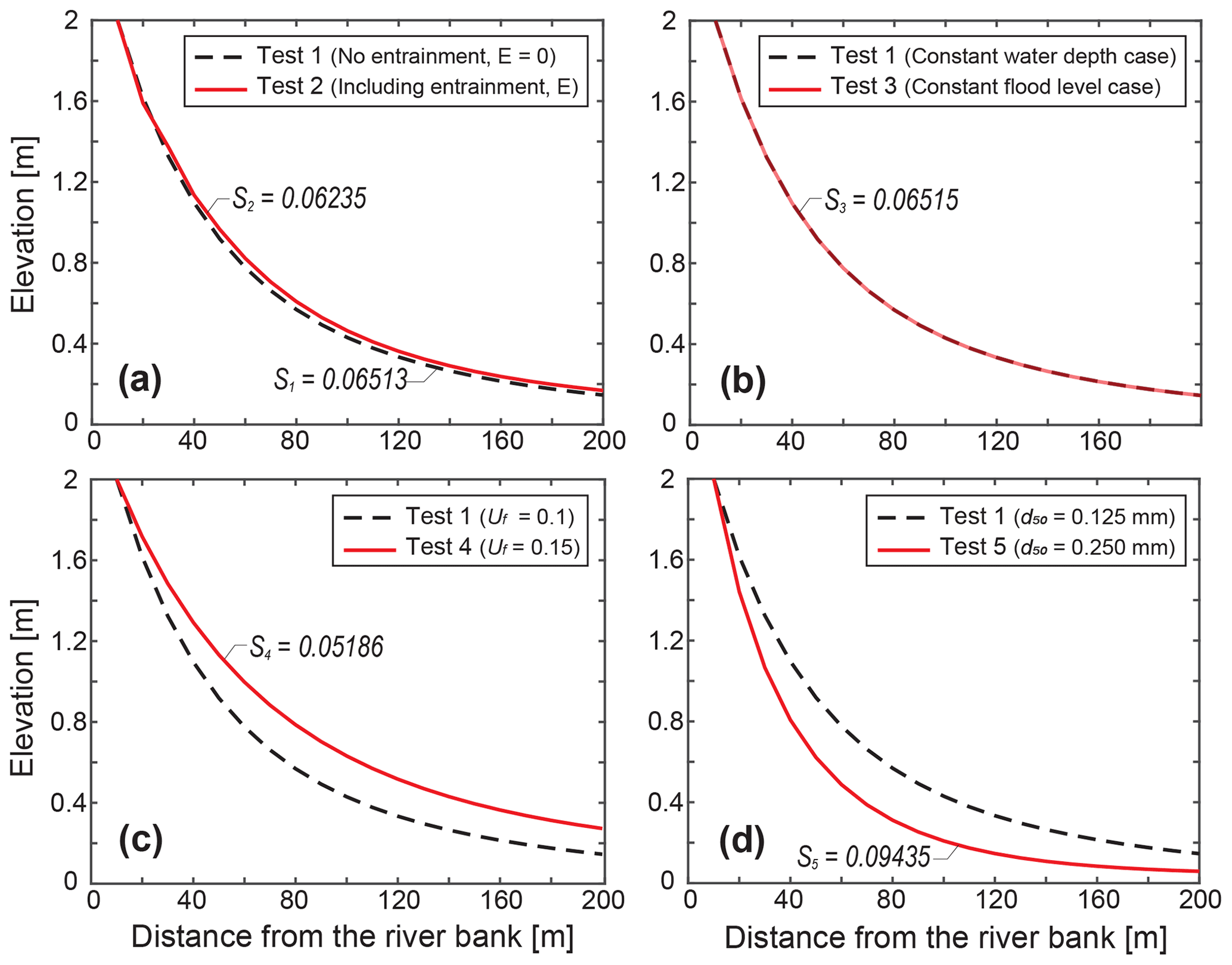
Figure 3Levee surface profiles taken at the end of each model. The dashed black line represents the results of Test 1 and the red lines are other test results.
3.2 Temporal variations of levee elevation
Figure 4 indicates changes in the levee surface elevation over time at the proximal location (grid node N=3) and the distal location (N=15) and suggests that the local surface elevations increase linearly showing there is no topographic feedback under simplified steady flow and constant sediment influx conditions. In terms of the aggradation rate, the gradients of the prototype model are and m min−1 at the proximal and distal positions, respectively. Each test result presents deviations from the results of the prototype although the slopes (aggradation rates) for Tests 2 and 3 are not significantly deviating from Test 1 (Fig. 4a and b). The depositional rates for Test 3 at both locations are lower than Test 1, and the normalized differences between Tests 1 and 3 are higher at the distal location than that of the proximal location (Fig. 4b). In Fig. 4c, the slope of the plot for the proximal location in Test 4 is lower than that of the prototype model, while the slope at the distal location is steeper than prototype one, which represents the increase in the flood-flow velocity enhances deposition in the distal locations. Meanwhile, the depositional rates of Test 5 with coarser sediment inputs both at the proximal and distal locations become lower than those of the Test 1 model (Fig. 4d).
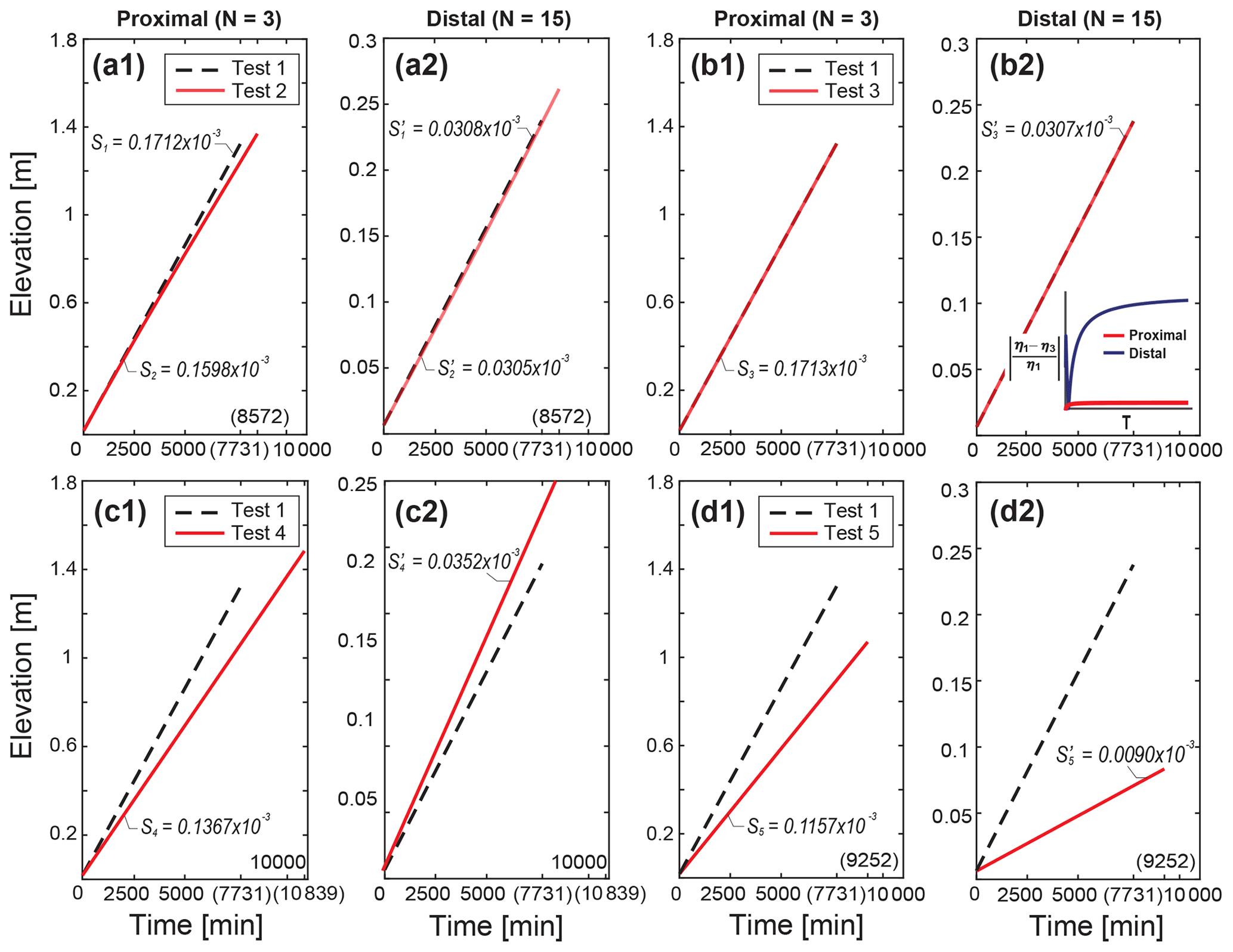
Figure 4Time series of levee elevations at the proximal (N=3, x=30 m) and distal (N=15, x=150 m) locations (solid red lines) against the results of Test 1 (dashed black lines) marked with each simulation time, T in parenthesis (Table 1). At each location, the scales of the two y-axes differ by (a) up to 1.8 m for the proximal and (b) 0.25 m for the distal locations. In (b), we additionally plot the normalized ratio of elevation differences between Tests 1 and 3 over time both at the proximal and distal locations.
3.3 Spatial trends in grain size of levee deposit
The plots of variations in grain sizes d50 (median grain size) and d90 (90 % finer grain size) versus distance from the channel–floodplain boundary show that the grain sizes decrease from the proximal to distal locations, which allow us to identify various downstream fining trends (Fig. 5). For Tests 2 and 3, d50 decreases from 0.08 to 0.04 mm and d90 changes from 0.12 to 0.06 mm over the 200 m width. Also, the reduction of d50 is relatively smooth as it approaches a specific value (0.04 mm) near the middle of the levee, whereas d90 keeps decreasing in the distal positions. In Fig. 5c, compared to Test 1, the d50 and d90 values in Test 4 are generally coarser, particularly at the distal locations since d90 decreases only by 0.03 mm across the levee. For Test 5 that has a coarser grain-size range, both d50 and d90 drop further than any other runs with rollover points in d90 on the more proximal position than in d50 (Fig. 5d).
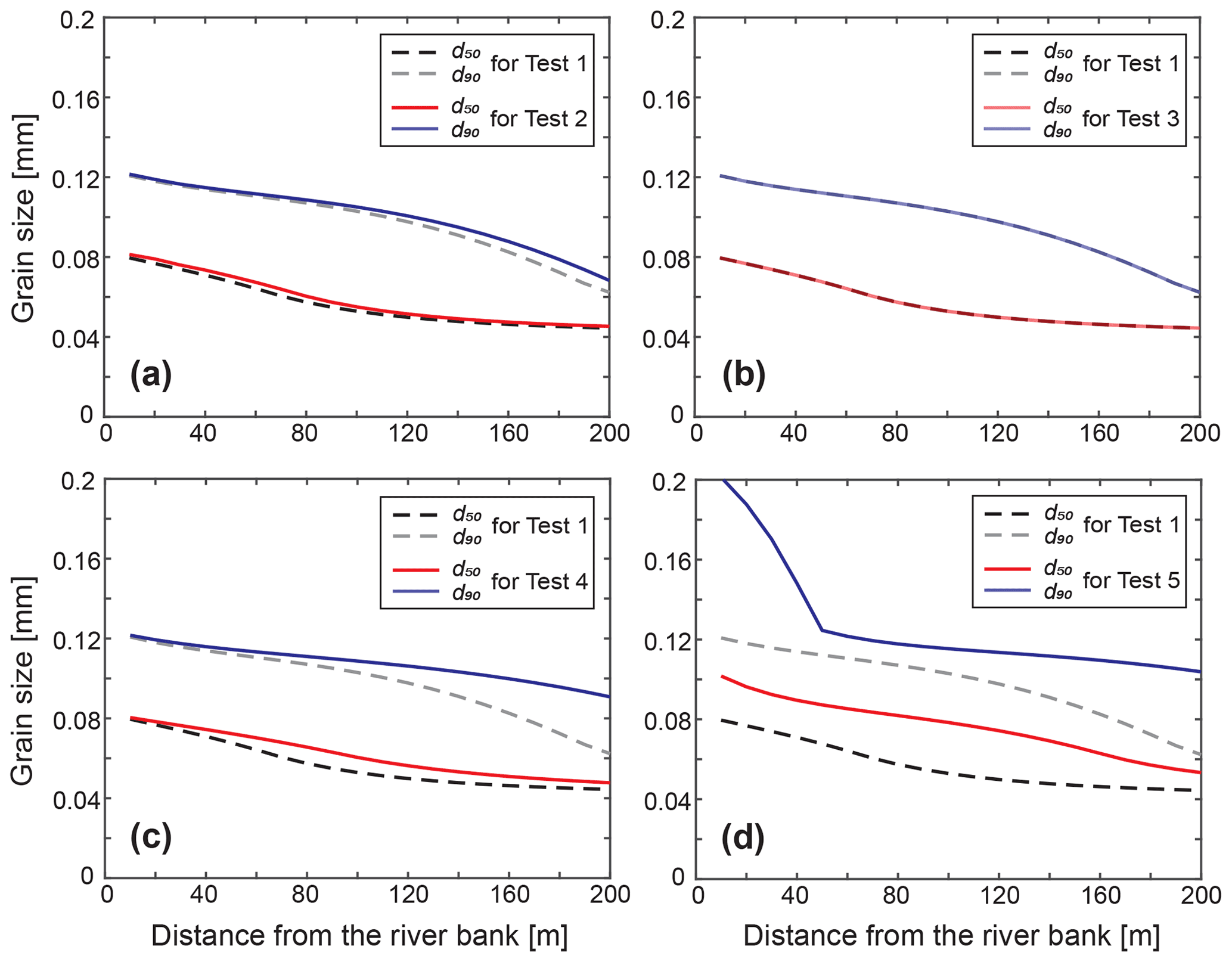
Figure 5The grain-size (d50 and d90) curves for the predicted levee deposits as a function of the distance from the channel-floodplain boundary. The two solid lines (red and blue) represent d50 and d90 for each test and the dashed lines (black and gray) are for Test 1, respectively.
3.4 Temporal variations of grain size of levee deposit
The model calculates d50 and d90 at the top deposit layer and records them every timestep at the assigned proximal and distal locations of the levees (Fig. 6). At both positions, the grain sizes d50 and d90 for most tests become finer quickly over the initial short run time and reach the equilibrium sizes except Test 2. The grain sizes in Test 2 rather increase over time, which can develop upward coarsening sequences (Fig. 6a). Test 3 has an overall similar fining pattern compared to the prototype result shown in Fig. 6b, but the grain-size values for all other tests are greater than Test 1. Both in the prototype model and in Test 3, the grain sizes d50 and d90 approach steady values of 0.0740 and 0.1158 mm at the proximal, 0.0469 and 0.0863 mm at the distal location, respectively. Figure 6c represents the results of Test 4 and shows different increasing patterns of d50 and d90 between the proximal and distal locations from Test 1. At the proximal position, the grain sizes of Test 4 merge to coarser values than Test 1, and display that the difference in d50 from the prototype model of 0.0024 mm is greater than that in d90 of 0.0017 mm. On the other hand, at the distal location, the difference of d90 between the prototype and Test 4 (0.0153 mm) is nearly three times as high as that of d50 (0.0050 mm). Test 5 also shows generally coarser grain sizes than the prototype model (Fig. 6d). We can notice that the difference of d90 between Tests 1 and 5 at the proximal location (0.0544 mm) is greater than that of d50 (0.0185 mm), while the differences of d50 and d90 at the distal location are 0.0189 and 0.0239 mm, respectively, which are relatively smaller. In addition, at the distal locations for all the tests, there are sharp drops in the grain size at the beginning of the runs due to the substantial grain size decreasing associated with the time that takes until the supplied suspended sediment transports to the distal location.

Figure 6Time series of grain sizes d50 and d90 at the top levee surface at the proximal (N=3, x=30 m) and distal (N=15, x=150 m) locations marked with each simulation time, T in parenthesis. The solid lines (red and blue) indicate the grain sizes d50 and d90 for each test, and the dashed lines (black and gray) are for Test 1, respectively.
The model produces concave-up surface profiles and shows proximal to distal fining trends, both of which are the typical features of natural levees (Brierley et al., 1997). As described in the field case studies of Cazanacli and Smith (1998) and Filgueira-Rivera et al. (2007), a faster overflow velocity would cause suspended sediment to transport farther across the floodplain building a relative gentler levee slope, while coarser grain sizes would be deposited closer to the channel margin and produce a steeper levee. Throughout the test runs, we found that levee evolution is not much different from the prototype when the model used entrainment (Test 2) or flood level conditions (Test 3). However, when the overflow velocity or the grain size of incoming suspended sediment to the floodplain increases (Tests 4 and 5), the levee shape significantly becomes gentler or steeper than the prototype model, which is mainly consistent with the observations reported in previous documents (Cazanacli and Smith, 1998; Filgueira-Rivera et al., 2007). Herein, we attribute the levee geometry and its grain-size trend to variable external forcings, such as flood hydraulics and suspended sediment supply.
4.1 Entrainment
Test 2, including the entrainment processes of sediment from the bed, is shown in (a) of each figure from Figs. 3a to 6a. Compared to Test 1, the aggradation rates for Test 2 are lower, especially at the proximal location and thus the final levee profile is also slightly lower at the proximal location while the final elevations are higher at the distal location (Figs. 3a and 4a). The overall grain sizes, d50 and d90 also become coarser than Test 1 and increase with time at each location (Figs. 5a and 6a). These suggest that the deposits near the levee crest were reworked and resuspended due to the entrainment and then transported further to the distal location (Fig. S1 in the Supplement). In particular, resuspension of the sediment on the surface by entrainment is more preferential for finer grain sizes with smaller settling velocities as expressed in Eqs. (7) and (8). At the proximal location, the resuspension makes changes more in d50 than d90 over time, which causes the clear upward coarsening sequences of d50 in Fig. 6a. It suggests that the upward coarsening sequences of d50 compared to d90 shown in the levee stratigraphy near the levee crest may better indicate an active re-entrainment process associated with the high erodibility of levee deposits. On the contrary, at the distal location, d50 has relatively low rates of increase over time compared to that of d90 as resuspended fines reaching the distal locations are more prone to bypassing the levee width without settling.
4.2 Water level condition
The prototype model has a constant water depth across the evolving levee on the floodplain, thereby the water surface is in phase with the sediment–surface topography. In contrast, Test 3 is a case of constant flood level which means the water elevation in the channel always defines the flood level across the floodplain (Fig. 1). Both test models use the advection settling of suspended sediment, but the setups in terms of the lateral water-surface slopes are similar to the “wide and dry” floodplain versus “narrow and wet” floodplains reported by Adams et al. (2004) as two flooding styles on the floodplain. The former represents a fast overflow along with a gradient in the water surface over the floodplain and the latter is associated with a filling of flood in a relatively narrow river valley, leading to no significant water surface gradient. In Test 3, as the levee gradually grows, the flood depth increases further away from the levee crest decreasing the flood velocity over time and thereby causing decreases in aggradation rates at the distal locations compared to Test 1. Meanwhile, the overflow depth at the levee crest is constant because the in-channel deposition is assumed to be equal to the levee crest aggradation (Fig. 4b). However, in general, there are no meaningful changes between the prototype and Test 3 in terms of the profile shape, aggradation rate, and grain-size distribution during the total run time until the levee crest reaches 2 m high (Fig. 3b through Fig. 6b). We inferred that in our model the water level does not affect the topographic and grain-size characteristics of the levee significantly in a way that increases in the water depth to the distal direction are compensated by decreases in the suspended concentration (cf. Figs. S2 and S3). Furthermore, if the flood level is equal everywhere in the floodplain, i.e., the hydraulic gradient is minimal so the flood flow should not be significant, and thus diffusion would be possibly dominant (Adams et al., 2004).
4.3 Overflow discharge
To evaluate the effect of hydraulic characteristics of flood in overbank deposits (James, 1985; Pierik et al., 2017; Wyżga, 1999), we set Test 4 such that it has a 1.5 times higher flood discharge which brings a 1.5 times higher flow velocity at the channel–floodplain boundary since the water depth is kept constant. This faster flow is more efficient to transport coarser sediment further into the floodplain on account of an increase in its competence. It also results in higher aggradation rates at the distal location than that at the proximal location in comparison with those of the prototype model, which is reflected in the gentler levee-profile slope (Figs. 3c and 4c). The gentler slope in Test 4 produces a larger volume under the profile compared to that in Test 1, which implies it needs more time to be filled until the levee crest height reaches 2 m in height. In the same context, the faster flow with regard to the grain-size distribution over the levee has more influence on the coarser grain size, d90 than d50 (Figs. 5c and 6c). When applying this trend to modern and/or ancient examples of levee deposits, the similarity in d90 between the proximal and distal levee deposits (Fig. 5c) can be interpreted to arise from the high flood-flow velocities. In Fig. 6c, the difference in d90 between the prototype and Test 4 at the distal location is substantially larger from the proximal location compared to that in d50. It can be inferred that the changes in grain size of the coarse grains e.g., d90 at somewhat distal locations serve as a better geomorphic indicator of an increase in overflow velocity.
4.4 Input grain size
Increasing grain size from d50=0.125 to 0.25 mm in Test 5 constructs a steeper slope of the levee as a consequence of faster settlement of coarser grains near the channel–floodplain boundary than Test 1 (Fig. 3d). This result can corroborate previous field observations in Cazanacli and Smith (1998) that coarser levees are likely to be steeper compared to finer levees. Here, note that we increase the near-bed grain size of the channel and the Rouse Eq. (2) determines the input grain-size distribution and sediment supply rate to the floodplain. The sediment mixture for Test 5 supplied to the floodplain has a higher peak at the median grain size with a narrow distribution (Fig. 2a), which drives an abrupt rollover point of d90 at the proximal location (Fig. 5d). Since the rollover point of d90 means that the coarser grain sizes are more rapidly consumed at the proximal location, the grain size d90 declines toward the distal location and the difference in d90 between Tests 1 and 5 also becomes similar to that of d50 at the distal location (Fig. 6d). Moreover, the sediment concentration in the top of the flood flow at the channel becomes smaller than Test 1 since coarser grains are located in the most bottom part of the Rouse profile, which causes a smaller sediment supply toward the floodplain. The decreasing sediment supply rate in Test 5 consequently leads to lower aggradation rates and thus a longer run time compared to Test 1 (Fig. 4d). However, considering the total sediment volume under the steep levee profile, Test 5 would build the levee until the crest reaches 2 m high with a smaller total sediment amount (i.e., a shorter total run time if the sediment supply rate is equal). Given the responses in the levee geometry and spatial grain-size distribution, it would therefore present the possibility of an increase in the overall grain size supplied into the floodplain when the thickness and d90 of the levee deposits markedly decline toward the distal locations from the main channel.
4.5 Control of levee geometry on river avulsion
Based on the findings from the current model, we estimate a possible linkage between avulsion frequency and levee geometry under given flood and grain-size conditions and explore subsequent associations of levee geometry with potential channel reoccupation. As river avulsion is known to be highly sensitive to the depositional patterns and adjacent floodplain morphology (Hajek and Edmonds, 2014; Jerolmack and Mohrig, 2007; Mohrig et al., 2000; Slingerland and Smith, 2004), this section can provide a first-order role of levee morphodynamics in the avulsion processes and, in turn, a source of insight regarding alleviation of damages from natural hazards related to river avulsion.
4.5.1 Avulsion frequency vs. levee slope
It is generally accepted that natural levee growth acts as an avulsion threshold (Jones and Schumm, 1999) whereby avulsion can initiate when an adjacent levee crest elevates about one channel depth in rivers, which is defined as a critical superelevation (Bryant et al., 1995; Jobe et al., 2020; Mohrig et al., 2000). In Fig. 7a, we apply this avulsion threshold to further quantify the avulsion frequency in our numerical modeling by measuring the total run time until the levee crest reaches one channel depth (Hc). A total 20 050 of levee models are replicated with ranges of the overflow velocities ( m s−1) and median grain sizes supplied into the floodplain ( mm), both of which exert important control over the levee geometry as Mohrig et al. (2000) and Jobe et al. (2020) postulated that superelevation is geometrically involved with levee slope (Fig. 7b). Here, we employ the constant water depth case and the total suspended sediment flux into the floodplain of 0.0003 m2 s−` for all the levee models. The entrainment effect is ignored for simplicity since neither of them significantly change the final levee geometry. We also assign a flood intermittency factor (If) of 0.002, assuming a flood recurrence interval of 3 years documented in Wyżga (1999) and scaling a flood lasting about 3 d to account for the estimated sediment flux in the floodplain. A characteristic levee slope (Sl) is defined here at an avulsion by using the total sediment volume per unit down-valley length under the levee profile as , even for the exceptional cases where the levee extends beyond the modeling floodplain width of 200 m.
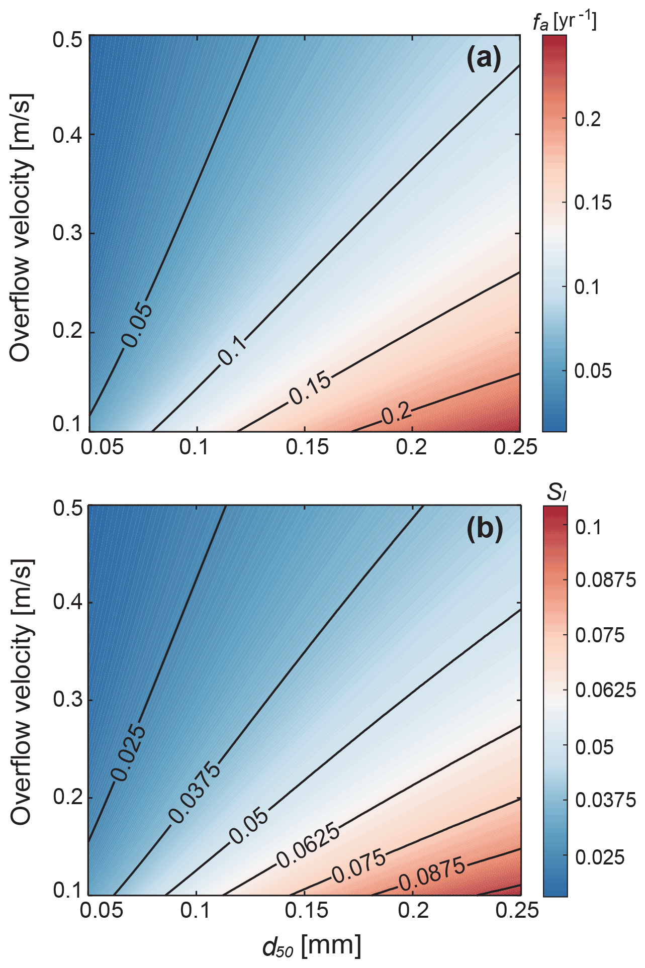
Figure 7Modeling results for (a) avulsion frequency, fa and (b) characteristic slope of levee, Sl as a function of the overflow velocity and input median grain size toward the floodplain. We set the intermittency factor, If=0.002 for all model runs.
4.5.2 Scaling analysis of avulsion frequency
To elucidate the correspondence between the levee geometry and avulsion frequency, we use a geometric scaling analysis of avulsion frequency. Avulsion time scale, Ta is estimated in the previous studies (Chadwick et al., 2020; Jerolmack and Mohrig, 2007; Reitz et al., 2010) as the time required for the levee crest height to reach the critical superelevation equal to one channel depth, Hc. In this sense, the avulsion frequency (fa) is given by
where If is the intermittency of floods, va is the vertical aggradation rate of in-channel bed which is the same as the aggradation rate of the levee crest in our study. The aggradation rate of levee crest is of the order of adopting the characteristic scales and ws for the average sediment concentration in overflow and the settling velocity of median grain size, respectively. If the sediment is transported dominantly in suspension, the sediment flux qs scales with where Uf and Hf are the overflow velocity and depth, respectively. Thus, we roughly rearrange Eq. (10) as
As noted in the previous Sect. 4.5.1, approximating the levee shape as a right triangle, the total sediment deposited in the levee that reaches the superelevation can be also represented using a mass balance with the characteristic levee slope, Sl:
On the left side of Eq. (12), as in Eq. (10) so the avulsion frequency can also be rewritten as
The foregoing analyses in Eq. (11) through Eq. (13) imply that the avulsion frequency depends on the characteristic levee slope (Sl), grain-settling velocity (ws), and overflow discharge (UfHf). We can also infer that the characteristic levee slope is proportional to the settling velocity of median grain size and water depth, and is inversely related to the overflow discharge (), which supports the similarity in the trend between the characteristic levee slope and avulsion frequency in our 1D levee-building model (Fig. 7). In addition, the settling velocity in Ferguson and Church (2004) derived from Stokes' law follows the relation of ws∼d2 and thus the levee slope as well as avulsion frequency is nonlinearly related to the median grain size.
Through the results of our numerical modeling and scaling analysis, it turns out that in the levee deposits, not only the critical superelevation is associated with the avulsion threshold, but the characteristic levee slope should be also taken into account in the avulsion processes. Some researchers suggested a floodplain slope ratio as an alternative approach for an avulsion criterion (Guccione et al., 1999; Jones and Schumm, 1999; Mackey and Bridge, 1995; Slingerland and Smith, 1998, 2004; Tornqvist and Bridge, 2002). The floodplain slope ratio is measured as a cross-valley slope relative to the down-channel or down-valley slope. In a large sense, the characteristic levee slope can be a proxy for the cross-valley component of the floodplain slope ratio. These avulsion controls, the floodplain slope ratios and superelevation from the modern rivers, are compared in the study by Mohrig et al. (2000). The authors observed that the distribution of normalized superelevation heights is less scattered than that of the floodplain slope ratios. This scatteredness compared to that in the floodplain slope ratios is even up to two orders of magnitude less (Mohrig et al., 2000), but still exists, and can be further explained by our relationship between the avulsion frequency and levee geometry. As in previously published studies (Bryant et al., 1995; Mackey and Bridge, 1995), a high sedimentation rate in the main channel leads to a high avulsion frequency. In this instance, the levee deposits also rapidly aggrade toward the local superelevation building steep levee slopes, consistent with our modeling results (see Fig. 7 and Eq. 13). The channel in turn can jump into a new flow path before preferentially constructing the distal part of the levee (i.e., backloading) and relatively steep levees would be less disturbed and remain in the abandoned channel producing wide variations in the floodplain slope ratio (Filgueira-Rivera et al., 2007). Hence, instead of adopting a single criterion, it is reasonable that both the superelevation and characteristic levee slope are taken into account to evaluate the channel avulsion processes (Tornqvist and Bridge, 2002).
4.5.3 Channel reoccupation vs. levee slope
When a river avulsion occurs, flow typically migrates into a preexisting channel or excavates a new flow path in the vicinity of a parent channel searching for low spots with the highest gradient advantage across a basin (Sahoo et al., 2020; Slingerland and Smith, 2004). In the sense that the former channels can serve as “attractors” to avulsing channels (Heller and Paola, 1996; Jerolmack and Paola, 2007; Mohrig et al., 2000; Reitz et al., 2010; Slingerland and Smith, 2004), it is common to recognize that most avulsion paths are prone to reoccupying the previously abandoned channels within the history of ancient avulsions, and in the modern rivers such as the Mississippi and Red River avulsions (Aslan et al., 2005; Edmonds et al., 2016; Hajek and Edmonds, 2014; Jerolmack and Paola, 2007). Hajek and Wolinsky (2012) suggested that the extent of proximal levee deposits located along the channel margin may also have an influence on avulsion behavior. We therefore propose that the levee geometry, i.e., the levee slopes along the abandoned channels have a critical role in the distribution of sediment on the floodplain that contains relicts of abandoned channels. It means, depending on the shape of the remnant levees, they can act to barricade the previously occupied channels promoting more channel reoccupation (Jerolmack and Paola, 2007; Mohrig et al., 2000).
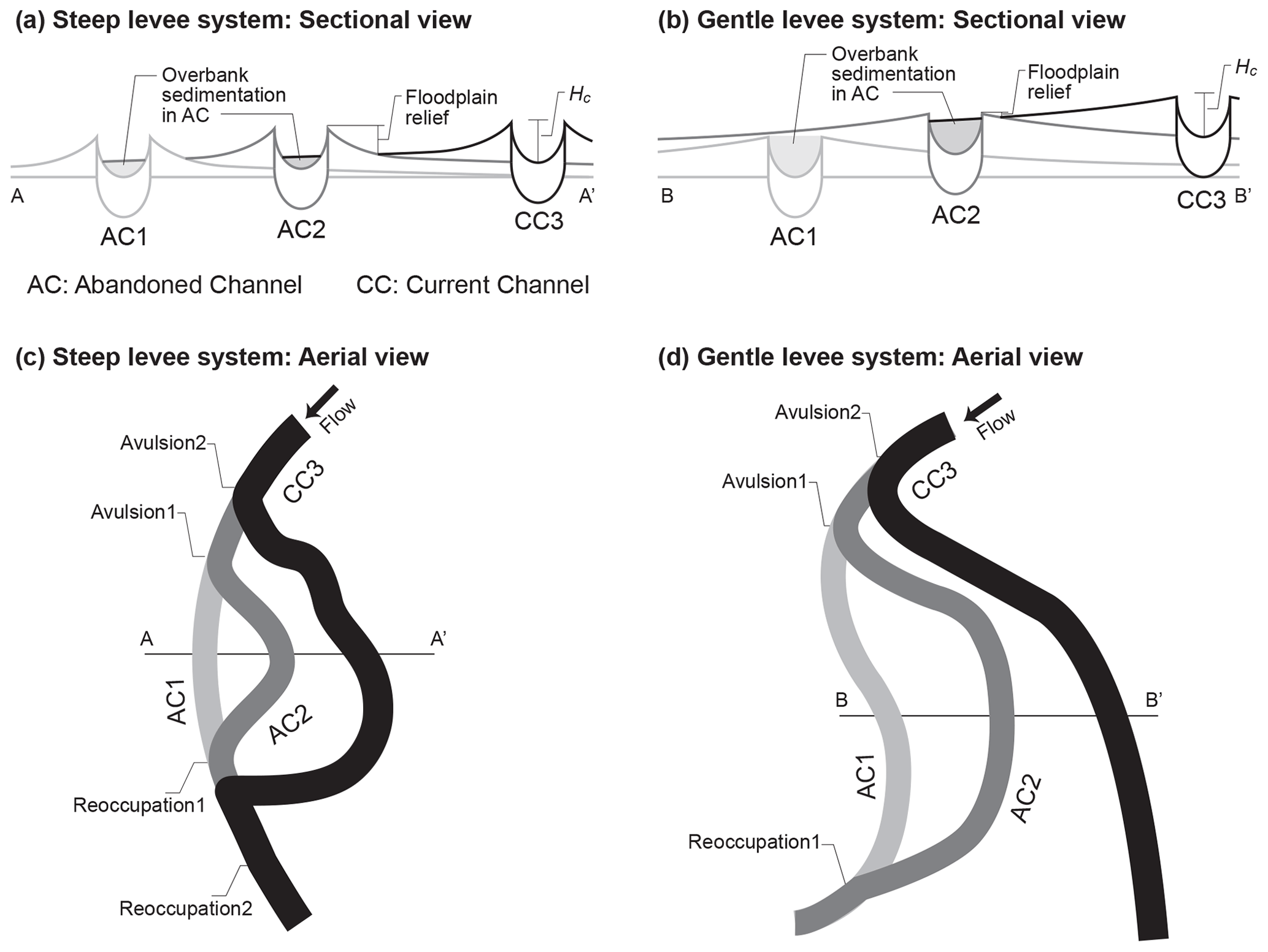
Figure 8Schematic of abandoned channel infillings under (a) steep levee system and (b) gentler levee system, and (c) annexational avulsion style with steeper levees, and (d) progradational avulsion with gentle levees both of which are modified from Slingerland and Smith (2004).
In the case of relatively steep levee slopes, the steep levees would extend to only limited distances to the floodplain, and consequently modify less of the initial local relief between the levee crests and adjacent floodplain (Fig. 8a). Hence, the abandoned channel topography surrounded by the high gradient levees can be protected from the influx of flood deposits. Furthermore, the steeper levees are associated with higher avulsion frequency, as described in Eq. (13), which indicates the avulsion would happen faster and leave the abandoned channel with less time to be filled. The abandoned channels maintain their topographic lows because they are filled with overbank deposits more slowly, and thus they would readily capture the flow and coalesce it into a new pathway (Hajek and Wolinsky, 2012; Mohrig et al., 2000). If so, it may increase the possibility for an active channel to find the topographic lows of preexisting channels and reoccupy them. The model of Jerolmack and Paola (2007) demonstrated that channel reoccupation repeatedly occurs within a limited number of active channels called the “active channel set”. This active channel set may occur in concert with steeper levee slopes along the floodplain channels taking advantage of remaining local conduits and producing multistory sand bodies (or vertical stacked patterns) in the ancient avulsion deposits (Jerolmack and Paola, 2007; Sahoo et al., 2020; Slingerland and Smith, 2004).
However, with the gentler levees, preexisting abandoned channels can be more vulnerable to being modified and smoothed, which is called “channel healing” or “annealing” as opposed to preserving the former topography (Guccione et al., 1999; Reitz et al., 2010; Slingerland and Smith, 2004). It is expected that relatively gentler levee deposits compared to the steeper ones would reach farther across the floodplain and increase the adjacent floodplain elevations, resulting in frequent overbank deposition into the abandoned channels (Fig. 8b). The low avulsion frequency predicted by Eq. (13) also intensifies topographic healing on any relict channels by providing more time for infilling with the overbank sediment. Once the abandoned channel topography is covered (i.e., smoothed by deposition), it tends to be left out for a long time deprived of any chance to encounter the active channels (Jerolmack and Paola, 2007). Due to the removal of topographic memories, a new channel is thereby more likely to incise the floodplain surface or to stay in the parent channel position even over the critical superelevation resulting in multilateral sand bodies in the avulsion stratigraphy (Jerolmack and Paola, 2007; Jones and Hajek, 2007).
4.5.4 Field applications for avulsion styles
The linkage between the levee geometry and channel reoccupation is applied to the following two field observations: one is a modern avulsive system and the other is from ancient fluvial strata. The former one, from published data by Valenza et al. (2020), investigates how the channel avulsion style evolves from the upstream to downstream reaches in modern rivers. In the study, they classify the avulsion styles into annexational and progradational avulsions (cf. Fig. 8); annexational avulsion occurs when the current flow returns to the remnant floodplain channels, and progradational avulsion occurs when a new avulsion channel is made with floodplain deposition (Edmonds et al., 2016; Hajek and Edmonds, 2014; Jones and Hajek, 2007; Slingerland and Smith, 2004). They quantify 63 avulsions across three sedimentary basins of the Andes, Himalayan, and New Guinean basins and suggest that most avulsions close to the mountain fronts generate annexational styles on braided rivers, while the avulsions of relatively further downstream basins mainly make progradational avulsions on meandering rivers. Valenza et al. (2020) provided several plausible reasons causing the shift in avulsion style, such as downstream changes in slope and downstream fining caused by selective deposition. Given these two changes, we speculate that the levee geometry may affect their reoccupation likelihoods of preexisting channels that are susceptible to the floodplain topography and surface roughness, e.g., depressions on the floodplain (Edmonds et al., 2016; Hajek and Edmonds, 2014; Hajek and Wolinsky, 2012; Jerolmack and Paola, 2007; Mohrig et al., 2000; Slingerland and Smith, 2004). Near the mountain fronts, any amount of coarser sediment overflows into the adjacent floodplain on account of selective deposition along the main stream. Moreover, a flooding type of upstream is traditionally characterized by intense rainfalls in a short period of time. The localized upstream flooding rapidly raises the overflow depth and pours out into the floodplain so that considerable coarser suspended sediment aggrade on the levee deposits. As a result, the upstream flash flooding and coarser grains would form non-cohesive steep slopes of levees which can defend formerly abandoned channels as topographic lows and create a favorable condition for annexational avulsions (Cazanacli and Smith, 1998; Hajek and Edmonds, 2014). The finer sediment at the downstream basins, on the contrary, is able to transport across the floodplain for a longer duration as the downstream flooding generally has a prolonged inundation period with a gradually increased flood level on a large scale. The suspended sediment would spread over a great distance, building cohesive levee deposits with a gentler shape (Cazanacli and Smith, 1998; Hudson and Heitmuller, 2003) and accelerating topographic healing of any scours or relic channels on the floodplain. By means of the erased topographic memories caused by the gentler-sloped levees, new streams have difficulty reoccupying the abandoned channels. Additionally, the cohesion of levee deposits due to the finer sediment in the downstream basins impedes the destruction of the robust levees on the current channel, which in turn will promote floodplain deposition and more progradational avulsions (Valenza et al., 2020).
The latter case of field observations is the Upper Cretaceous alluvial to coastal plain deposits of the Blackhawk Formation in Wasatch Plateau, Central Utah, USA. Previous studies on this ancient fluvial strata have identified that the fluvial sand bodies in the upper Blackhawk Formation contain vertically stacked and laterally offset channelized patterns in response to large-scale avulsion processes (Flood and Hampson, 2014, 2015; Hampson et al., 2012, 2013; Sahoo et al., 2020). Sahoo et al. (2020) highlighted that in terms of channelized sand bodies, their internal architectures, paleochannel mobility, and their distribution and stacking patterns in strata are correlated with each other. They interpreted that vertically stacking single-story sand bodies indicate channel reoccupations with low channel mobility, and isolated or lateral offset patterns of multilateral sand bodies represent the regional avulsions (randomly choose their new flowpath) with high mobility of channels (Heller and Paola, 1996). In our model, this can be explained as a result of the geomorphic difference in alluvial ridges. Since the channel mobility, M is defined as the ratio of lateral migration to avulsion timescales (Jerolmack and Mohrig, 2007), it is possible that the channel mobility affects the formation of levee shape which is negatively correlated with the avulsion timescale as presented in Eq. (12). Tooth et al. (2007) also has exhibited that the lateral accretion of a channel can limit the vertical aggradation on the floodplain and observed new avulsion channels mainly formed by incision of the floodplain in Klip River. We hence surmise that high channel lateral mobility could allow relatively less time for vertical accretion of levee deposits and thus build only gentler slope, whereas low channel lateral mobility could linger and give enough time to build relatively steeper levees. This brings us a new potential linkage between the channel lateral mobility and channel reoccupation (also channel stacking patterns). Yet, it goes quite far beyond the scope of this paper and may bring another future research topic that requires more confirmation based on field measurements. Furthermore, if we are able to recognize detailed floodplain internal architectures and alluvial ridge configurations in the stratigraphic records, it would aid in deciphering the ancient floodplain conditions, e.g., water and sediment supplies into the floodplain. Although more field investigations need to be undertaken to verify our hypotheses, the levee stratigraphic records that have been less of interest may still give us practical hints in predicting and reconstructing the river systems related to avulsion processes.
4.6 Limitations of 1D levee-building model
Our 1D levee-building model is used to examine the dynamic evolution of fluvial levees describing their resultant topography and grain-size trends over time. Even though our model offers the fundamental mechanisms of levee geomorphology and their relationship to river avulsion processes, challenges have remained to fully reflect the complexity of depositional processes in the levee–floodplain complex. Like other 1D hydrodynamic models, the current model cannot thoroughly reproduce the dynamics of flood conditions since the model can overestimate the inundation extents by ignoring the friction parameters and infiltration processes (Tayefi et al., 2007). Additionally, we do not account for other factors associated with vegetation, cohesion, and preexisting floodplain topography, which can affect the suspended sediment load across the floodplain and drainage development in the flood basin, and eventually impact the levee formations and the infilling of abandoned channels (Boechat Albernaz et al., 2020; Branß et al., 2022; Kleinhans et al., 2018; Mohrig et al., 2000).
The current model is based on the following simplifying assumptions: (1) a constant suspended flux with normally distributed grain sizes that flow into the floodplain and (2) a cross-sectional levee profile that evolves symmetrically in both sides of the channel. Within the natural river systems, bedload sediment transport can be important for some levee building processes, especially in meandering rivers. The alluvial ridge which contains levee deposits can be developed by both suspended and bedload sediment deposition and would be varied by the size of the bank (inner and outer bank) and channel lateral migration rate (Ielpi et al., 2020; Toonen et al., 2012; van Dijk et al., 2013). The fluvial levees are thus generally unpaired along sinuous channels due to the differences in lateral erosional and depositional processes (Skolasiñska, 2014; Wyżga, 1999). However, the current model has not yet incorporated other components of the alluvial ridge that can be amalgamated with point bar deposits or crevasse splays, etc., which may possibly alter the levee geometry rather than a simplified levee deposit. Still, we believe that isolating levee formation from the channel bank dynamics can allow us to infer the effects of levee geometry on the avulsion behaviors and abandoned channel fills on behalf of the alluvial ridge topography. We also note that the aggradation rates set equal for the in-channel and levee crest can be another limitation in the model, both of which can be varied in nature and influence the overbank grain-size distribution and the avulsion conditions (Ganti et al., 2016; Nicholas et al., 2018). This complexity in channel–floodplain hydrodynamics can cause discrepancies between our simplified modeling approach and natural levee evolutions. Nevertheless, our 1D levee-building model does provide significant implications for further understanding of the levee formation and its possible linkage with avulsion processes and may give an important basis for enhancing future models along with more accurate field parameters.
The fluvial levee evolution under various boundary conditions was investigated by using the numerical levee-building model with the advection settling of suspended sediment. The current levee-building model allows us to establish what determines the levee geometry and delineate the relationship between the levee geometry and avulsion behaviors. Briefly, our main conclusions can be summarized as follows:
-
Overflow discharge and incoming sediment grain size into floodplain exert first-order controls on the levee geometry. The results show that a relatively gentler shape of the levee is associated with the faster flooded flow and a steeper slope is associated with coarser suspended sediment. The levee geometry that can reflect the flood hydraulics and/or grain-size distribution in the channel may work as a good indicator of the paleo-environment in the stratigraphic records.
-
There is a significant correlation between the avulsion frequency and levee geometry in respect of overflow properties. The avulsion frequency is proportional to the characteristic levee slope and median grain size of overbank suspended sediment but negatively correlated with overflow discharge. With a high avulsion frequency, a steeper levee is more likely to lead to the reoccupation of the previously abandoned paths. In contrast, a gentler levee with low frequency causes smoothing of the abandoned channel topography, and then a new path would be made on the floodplain.
-
We propose a new approach concerning levee morphology to understand the transition of river avulsion styles in the modern avulsive system reported by Valenza et al. (2020). From upstream to downstream, the levee geometry which can be modified due to downstream fining and decreasing stream power, is potentially involved in the shift of the avulsion style from annexational to progradational avulsions. We further suggest that the geomorphic difference in alluvial ridges may be related to the channel mobilities and their stacking patterns of sand bodies and explain the case of the upper Cretaceous Blackhawk Formation in Wasatch Plateau, Central Utah, USA described in Sahoo et al. (2020). Even though more field data will be needed to fully test our hypotheses, the implications can nourish our knowledge of avulsion processes linking with the levee geometry. Therefore, this study may encourage additional studies of natural levees for better prediction of avulsion behaviors and their flood risks.
The following list includes variables with symbols L, M, and T, representing dimensions of length, mass, and time, respectively.
| a | Reference near bed height, [L]. |
| Near bed concentration at z=a in channel, [–] | |
| Near bed concentration in floodplain, [–]. | |
| Suspended sediment concentration in channel, | |
| [–]. | |
| Suspended sediment concentration in floodplain, | |
| [–]. | |
| Ds | Depositional rate, [L T−1]. |
| di | ith grain size, [L]. |
| d50 | Median grain size, [L]. |
| Ei | Dimensionless entrainment rate of ith grain |
| size, [–]. | |
| Es | Entrainment rate, [L T−1]. |
| Eui | Dimensionless entrainment rate of ith grain |
| size per unit area, [–]. | |
| Fi | ith grain size fraction, [–]. |
| fa | Avulsion frequency, [T−1] |
| g | Gravitational acceleration, [L2 T−1]. |
| Hc | Channel depth, [L]. |
| Hf | Overflow depth, [L]. |
| Ht | Total flow depth, [L]. |
| If | Flood intermittency, [–]. |
| L | Floodplain width, [L]. |
| Pi | Rouse number, [–]. |
| qs | Volume transport of suspended sediment per |
| unit width, [L2 T−1]. | |
| qso | Total sediment flux at the channel-floodplain |
| boundary, [L2 T−1]. | |
| qts | Total sediment flux of channel, [L2 T−1]. |
| qw | Water flux, [L2 T−1]. |
| R | Submerged specific gravity, [–]. |
| Repi | Renold's particle number, [–]. |
| Sf | Initial slope of floodplain, [–]. |
| Sc | Initial slope of main channel, [–]. |
| Sl | Characteristic slope of levee deposit, [–]. |
| Ta | Avulsion time scale, [T]. |
| t | Time, [T]. |
| Uf | Overflow velocity, [L T−1]. |
| u* | Shear velocity, [L T−1]. |
| u*s | Shear velocity associated with skin friction, |
| [L T−1]. | |
| va | Aggradation rate of channel bed, [L T−1]. |
| ws | Particle settling velocity, [L T−1]. |
| x | Coordinate to the distal direction of floodplain, |
| [L]. | |
| z | Reference elevation, [L]. |
| Zui | Similarity variable for the ith grain-size range, |
| [–]. | |
| η | Bed elevation, [L]. |
| ηi | Elevation of ith node, [L]. |
| η0 | Elevation at levee crest, [L]. |
| κ | Von Karman constant, [–]. |
| λm | Straining parameter, [–]. |
| λp | Porosity of deposition, [–]. |
| ν | Kinematic viscosity of fluid, [L2 T−1]. |
| ρs | Sediment density, [M L−3]. |
| ρw | Water density, [M L−3]. |
| σ | Standard deviation, [–]. |
The MATLAB codes used in the one-dimensional levee-building model and associated tests are openly available at https://doi.org/10.5281/zenodo.6802570 (Han and Kim, 2022a).
The modeling output data are archived and openly available at https://doi.org/10.5281/zenodo.6822067 (Han and Kim, 2022b).
The supplement related to this article is available online at: https://doi.org/10.5194/esurf-10-743-2022-supplement.
JH designed, conducted the computer code with the help of WK; analyzed the model results; and wrote the manuscript. WK motivated, conceptualized the study; developed methodology; acquired funding and supervised the research; and revised the paper. Both authors contributed to the discussion and editing of the manuscript writing.
The contact author has declared that neither of the authors has any competing interests.
Publisher's note: Copernicus Publications remains neutral with regard to jurisdictional claims in published maps and institutional affiliations.
We thank the National Research Foundation of Korea (NRF) and the Yonsei University Research Fund for research support. We also thank the editor Paola Passalacqua and two reviewers, Douglas Edmonds and one anonymous referee for thoughtful discussions and constructive comments which tremendously helped to improve and clarify this paper.
This research has been supported by the Basic Science Program through the National Research Foundation of Korea (grant nos. NRF-2020R1A2C1006083 and NRF-2017R1A6A1A07015374) and in part by the Yonsei University Research Fund of 2021 (grant no. 2020-22-0507).
This paper was edited by Paola Passalacqua and reviewed by Douglas Edmonds and one anonymous referee.
Adams, P. N., Slingerland, R. L., and Smith, N. D.: Variations in natural levee morphology in anastomosed channel flood plain complexes, Geomorphology, 61, 127–142, https://doi.org/10.1016/j.geomorph.2003.10.005, 2004.
Allen, J. R. L.: A Review of the Origin and Characteristics of Recent Alluvial Sediments, Sedimentology, 5, 89–191, https://doi.org/10.1111/j.1365-3091.1965.tb01561.x, 1965.
Aslan, A., Autin, W. J., and Blum, M. D.: Causes of river avulsion: insights from the late Holocene avulsion history of the Mississippi River, USA, J. Sediment. Res., 75, 650–664, https://doi.org/10.2110/jsr.2005.053, 2005.
Boechat Albernaz, M., Roelofs, L., Pierik, H. J., and Kleinhans, M. G.: Natural levee evolution in vegetated fluvial-tidal environments, Earth Surf. Proc. Land., 45, 3824–3841, https://doi.org/10.1002/esp.5003, 2020.
Branß, T., Núñez-González, F., and Aberle, J.: Fluvial levees in compound channels: a review on formation processes and the impact of bedforms and vegetation, Environ. Fluid Mech., 22, 559—585, https://doi.org/10.1007/s10652-022-09850-9, 2022.
Brierley, G. J., Ferguson, R. J., and Woolfe, K. J.: What is a fluvial levee?, Sediment. Geol., 114, 1–9, https://doi.org/10.1016/S0037-0738(97)00114-0, 1997.
Bryant, M., Falk, P., and Paola, C.: Experimental study of avulsion frequency and rate of deposition, Geology, 23, 365–368, https://doi.org/10.1130/0091-7613(1995)023<0365:Esoafa>2.3.Co;2, 1995.
Cazanacli, D. and Smith, N. D.: A study of morphology and texture of natural levees – Cumberland Marshes, Saskatchewan, Canada, Geomorphology, 25, 43–55, https://doi.org/10.1016/S0169-555x(98)00032-4, 1998.
Chadwick, A. J., Lamb, M. P., and Ganti, V.: Accelerated river avulsion frequency on lowland deltas due to sea-level rise, P. Natl. Acad. Sci. USA, 117, 17584–17590, https://doi.org/10.1073/pnas.1912351117, 2020.
Edmonds, D. A., Hajek, E. A., Downton, N., and Bryk, A. B.: Avulsion flow-path selection on rivers in foreland basins, Geology, 44, 695–698, https://doi.org/10.1130/g38082.1, 2016.
Ferguson, R. I. and Church, M.: A Simple Universal Equation for Grain Settling Velocity, J. Sediment. Res., 74, 933–937, https://doi.org/10.1306/051204740933, 2004.
Ferguson, R. J. and Brierley, G. J.: Levee morphology and sedimentology along the lower Tuross River, south-eastern Australia, Sedimentology, 46, 627-648, doi: 10.1046/j.1365-3091.1999.00235.x, 1999.
Filgueira-Rivera, M., Smith, N. D., and Slingerland, R. L.: Controls on natural levée development in the Columbia River, British Columbia, Canada, Sedimentology, 54, 905–919, https://doi.org/10.1111/j.1365-3091.2007.00865.x, 2007.
Flood, Y. S. and Hampson, G. J.: Facies And Architectural Analysis To Interpret Avulsion Style and Variability: Upper Cretaceous Blackhawk Formation, Wasatch Plateau, Central Utah, U.S.A., J. Sediment. Res., 84, 743–762, https://doi.org/10.2110/jsr.2014.59, 2014.
Flood, Y. S. and Hampson, G. J.: Quantitative Analysis of the Dimensions and Distribution of Channelized Fluvial Sandbodies Within A Large Outcrop Dataset: Upper Cretaceous Blackhawk Formation, Wasatch Plateau, Central Utah, U.S.A., J. Sediment. Res., 85, 315–336, https://doi.org/10.2110/jsr.2015.25, 2015.
Ganti, V., Chadwick, A. J., Hassenruck-Gudipati, H. J., and Lamb, M. P.: Avulsion cycles and their stratigraphic signature on an experimental backwater-controlled delta, J. Geophys. Res.-Earth, 121, 1651–1675, https://doi.org/10.1002/2016JF003915, 2016.
Garcia, M. and Parker, G.: Entrainment of Bed Sediment into Suspension, J. Hydraul. Eng., 117, 414–435, https://doi.org/10.1061/(asce)0733-9429(1991)117:4(414), 1991.
Guccione, M., Burford, M., and Kendall, J.: Pemiscot Bayou, a large distributary of the Mississippi River and a possible failed avulsion, in: Fluvial sedimentology VI, 28, Wiley, 211–220, https://doi.org/10.1002/9781444304213.ch16, 1999.
Gugliotta, M., Saito, Y., Ben, B., Sieng, S., and Oliver, T. S. N.: Sedimentology of Late Holocene fluvial levee and point-bar deposits from the Cambodian tract of the Mekong River, J. Geol. Soc., 175, 176–186, https://doi.org/10.1144/jgs2017-047, 2018.
Guy, H. P.: Fluvial sediment concepts, US Government Printing Office, https://doi.org/10.3133/twri03C1, 1970.
Hajek, E. A. and Edmonds, D. A.: Is river avulsion style controlled by floodplain morphodynamics?, Geology, 42, 199–202, https://doi.org/10.1130/g35045.1, 2014.
Hajek, E. A. and Wolinsky, M. A.: Simplified process modeling of river avulsion and alluvial architecture: Connecting models and field data, Sediment. Geol., 257–260, 1–30, https://doi.org/10.1016/j.sedgeo.2011.09.005, 2012.
Hampson, G. J., Royhan Gani, M., Sahoo, H., Rittersbacher, A., Irfan, N., Ranson, A., Jewell, T. O., Gani, N. D. S., Howell, J. A., Buckley, S. J., and Bracken, B.: Controls on large-scale patterns of fluvial sandbody distribution in alluvial to coastal plain strata: Upper Cretaceous Blackhawk Formation, Wasatch Plateau, Central Utah, USA, Sedimentology, 59, 2226–2258, https://doi.org/10.1111/j.1365-3091.2012.01342.x, 2012.
Hampson, G. J., Jewell, T. O., Irfan, N., Gani, M. R., and Bracken, B.: Modest Change In Fluvial Style With Varying Accommodation In Regressive Alluvial-To-Coastal-Plain Wedge: Upper Cretaceous Blackhawk Formation, Wasatch Plateau, Central Utah, U.S.A., J. Sediment. Res., 83, 145–169, https://doi.org/10.2110/jsr.2013.8, 2013.
Han, J. and Kim, W.: Han2021_1DLeveeBuildingModel (v1.0.0), Zenodo [code], https://doi.org/10.5281/zenodo.6802570, 2022a.
Han, J. and Kim, W.: LBM_dataset, Zenodo [data set], https://doi.org/10.5281/zenodo.6822067, 2022b.
Heller, P. L. and Paola, C.: Downstream changes in alluvial architecture: An exploration of controls on channel-stacking patterns, J. Sediment. Res., 66, 297–306, https://doi.org/10.1306/d4268333-2b26-11d7-8648000102c1865d, 1996.
Hudson, P. F. and Heitmuller, F. T.: Local-and watershed-scale controls on the spatial variability of natural levee deposits in a large fine-grained floodplain: Lower Panuco Basin, Mexico, Geomorphology, 56, 255–269, https://doi.org/10.1016/S0169-555X(03)00155-7, 2003.
Ielpi, A., Lapôtre, M. G., Finotello, A., Ghinassi, M., and D'Alpaos, A.: Channel mobility drives a diverse stratigraphic architecture in the dryland Mojave River (California, USA), Earth Surf. Proc. Land., 45, 1717–1731, https://doi.org/10.1002/esp.4841, 2020.
Imran, J., Parker, G., and Katopodes, N.: A numerical model of channel inception on submarine fans, J. Geophys. Rese.-Oceans, 103, 1219–1238, https://doi.org/10.1029/97jc01721, 1998.
James, C. S.: Sediment Transfer to Overbank Sections, J. Hydraul. Res., 23, 435–452, https://doi.org/10.1080/00221688509499337, 1985.
Jerolmack, D. J. and Mohrig, D.: Conditions for branching in depositional rivers, Geology, 35, 463–466, https://doi.org/10.1130/g23308a.1, 2007.
Jerolmack, D. J. and Paola, C.: Complexity in a cellular model of river avulsion, Geomorphology, 91, 259–270, https://doi.org/10.1016/j.geomorph.2007.04.022, 2007.
Jobe, Z. R., Howes, N. C., Straub, K. M., Cai, D., Deng, H., Laugier, F. J., Pettinga, L. A., and Shumaker, L. E.: Comparing Aggradation, Superelevation, and Avulsion Frequency of Submarine and Fluvial Channels, Front Earth Sci.-Switz., 8, 1–22, https://doi.org/10.3389/feart.2020.00053, 2020.
Johnston, G. H., David, S. R., and Edmonds, D. A.: Connecting Fluvial Levee Deposition to Flood-Basin Hydrology, J. Geophys. Res.-Earth, 124, 1996–2012, https://doi.org/10.1029/2019jf005014, 2019.
Jones, H. and Hajek, E.: Characterizing avulsion stratigraphy in ancient alluvial deposits, Sediment. Geol., 202, 124–137, https://doi.org/10.1016/j.sedgeo.2007.02.003, 2007.
Jones, L. and Schumm, S.: Causes of avulsion: an overview, in: Fluvial sedimentology VI, 28, Wiley, 171–178, https://doi.org/10.1002/9781444304213.ch13, 1999.
Kleinhans, M. G., de Vries, B., Braat, L., and van Oorschot, M.: Living landscapes: Muddy and vegetated floodplain effects on fluvial pattern in an incised river, Earth Surf. Proc. Land., 43, 2948–2963, https://doi.org/10.1002/esp.4437, 2018.
Mackey, S. D. and Bridge, J. S.: Three-dimensional model of alluvial stratigraphy; theory and applications, J. Sediment. Res., 65, 7–31, https://doi.org/10.1306/d42681d5-2b26-11d7-8648000102c1865d, 1995.
Mishra, K. and Sinha, R.: Flood risk assessment in the Kosi megafan using multi-criteria decision analysis: A hydro-geomorphic approach, Geomorphology, 350, 106861, https://doi.org/10.1016/j.geomorph.2019.106861, 2020.
Mohrig, D., Heller, P. L., Paola, C., and Lyons, W. J.: Interpreting avulsion process from ancient alluvial sequences: Guadalope-Matarranya system (northern Spain) and Wasatch Formation (western Colorado), Geol. Soc. Am. Bull., 112, 1787–1803, https://doi.org/10.1130/0016-7606(2000)112<1787:Iapfaa>2.0.Co;2, 2000.
Nicholas, A., Aalto, R., Sambrook Smith, G., and Schwendel, A.: Hydrodynamic controls on alluvial ridge construction and avulsion likelihood in meandering river floodplains, Geology, 46, 639–642, https://doi.org/10.1130/G40104.1, 2018.
Pearce, F.: When the levees break, Science, 372, 676–679, https://doi.org/10.1126/science.372.6543.676, 2021.
Pierik, H., Stouthamer, E., and Cohen, K.: Natural levee evolution in the Rhine-Meuse delta, the Netherlands, during the first millennium CE, Geomorphology, 295, 215–234, https://doi.org/10.1016/j.geomorph.2017.07.003, 2017.
Pizzuto, J. E.: Sediment Diffusion during Overbank Flows, Sedimentology, 34, 301–317, https://doi.org/10.1111/j.1365-3091.1987.tb00779.x, 1987.
Pruszak, Z., Van Ninh, P., Szmytkiewicz, M., Hung, N. M., and Ostrowski, R.: Hydrology and morphology of two river mouth regions (temperate Vistula Delta and subtropical Red River Delta), Oceanologia, 47, 365–385, https://doi.org/10.1134/S0097807816040084, 2005.
Reitz, M. D., Jerolmack, D. J., and Swenson, J. B.: Flooding and flow path selection on alluvial fans and deltas, Geophys. Res. Lett., 37, L06401, https://doi.org/10.1029/2009gl041985, 2010.
Rouse, H.: Modern conceptions of the mechanics of fluid turbulence, T. ASCE, 102, 463–505, https://doi.org/10.1061/taceat.0004872, 1937.
Sahoo, H., Gani, M. R., Gani, N. D., Hampson, G. J., Howell, J. A., Storms, J. E. A., Martinius, A. W., and Buckley, S. J.: Predictable patterns in stacking and distribution of channelized fluvial sand bodies linked to channel mobility and avulsion processes, Geology, 48, 903–907, https://doi.org/10.1130/g47236.1, 2020.
Skolasiñska, K.: Inquiry of levee formation by grain size analysis – A case study from the Warta River (central Poland), Catena, 122, 103–110, https://doi.org/10.1016/j.catena.2014.06.014, 2014.
Slingerland, R. and Smith, N. D.: Necessary conditions for a meandering-river avulsion, Geology, 26, 435–438, https://doi.org/10.1130/0091-7613(1998)026<0435:Ncfamr>2.3.Co;2, 1998.
Slingerland, R. and Smith, N. D.: River Avulsions and Their Deposits, Annu. Rev. Earth Planet. Sci., 32, 257–285, https://doi.org/10.1146/annurev.earth.32.101802.120201, 2004.
Smith, N. D. and Pérez-Arlucea, M.: Natural levee deposition during the 2005 flood of the Saskatchewan River, Geomorphology, 101, 583–594, https://doi.org/10.1016/j.geomorph.2008.02.009, 2008.
Stouthamer, E. and Berendsen, H. J.: Avulsion frequency, avulsion duration, and interavulsion period of Holocene channel belts in the Rhine-Meuse delta, the Netherlands, J. Sediment. Res., 71, 589–598, https://doi.org/10.1306/112100710589, 2001.
Tayefi, V., Lane, S., Hardy, R., and Yu, D.: A comparison of one- and two-dimensional approaches to modelling flood inundation over complex upland floodplains, Hydrol. Process., 21, 3190–3202, https://doi.org/10.1002/hyp.6523, 2007.
Toonen, W. H., Kleinhans, M. G., and Cohen, K. M.: Sedimentary architecture of abandoned channel fills, Earth Surf. Proc. Land., 37, 459–472, https://doi.org/10.1002/esp.3189, 2012.
Tooth, S., Rodnight, H., Duller, G. A., McCarthy, T. S., Marren, P. M., and Brandt, D.: Chronology and controls of avulsion along a mixed bedrock-alluvial river, Geol. Soc. Am. Bull., 119, 452–461, https://doi.org/10.1130/B26032.1, 2007.
Tornqvist, T. E. and Bridge, J. S.: Spatial variation of overbank aggradation rate and its influence on avulsion frequency, Sedimentology, 49, 891–905, https://doi.org/10.1046/j.1365-3091.2002.00478.x, 2002.
Valenza, J. M., Edmonds, D. A., Hwang, T., and Roy, S.: Downstream changes in river avulsion style are related to channel morphology, Nat. Commun., 11, 2116, https://doi.org/10.1038/s41467-020-15859-9, 2020.
van Dijk, W. M., van de Lageweg, W. I., and Kleinhans, M. G.: Formation of a cohesive floodplain in a dynamic experimental meandering river, Earth Surf. Proc. Land., 38, 1550–1565, https://doi.org/10.31223/osf.io/8dhv2, 2013.
Wolman, M. G. and Leopold, L. B.: River flood plains: some observations on their formation, Report 282C, USGS, Washington, DC, 87–109, https://doi.org/10.3133/pp282C, 1957.
Wyżga, B.: Estimating mean flow velocity in channel and floodplain areas and its use for explaining the pattern of overbank deposition and floodplain retention, Geomorphology, 28, 281–297, https://doi.org/10.1016/S0169-555X(98)00110-X, 1999.