the Creative Commons Attribution 4.0 License.
the Creative Commons Attribution 4.0 License.
 | 26 Feb 2024
Coevolving edge rounding and shape of glacial erratics: the case of Shap granite, UK
The size distributions and the shapes of detrital rock clasts can shed light on the environmental history of the clast assemblages and the processes responsible for clast comminution. For example, mechanical fracture due to the stresses imposed on a basal rock surface by a body of flowing glacial ice releases initial “parent” shapes of large blocks of rock from an outcrop, which then are modified by the mechanics of abrasion and fracture during subglacial transport. The latter processes produce subsequent generations of shapes, possibly distinct in form from the parent blocks. A complete understanding of both the processes responsible for block shape changes and the trends in shape adjustment with time and distance away from the source outcrop is lacking. Field data on edge rounding and shape changes of Shap granite blocks (dispersed by Devensian ice eastwards from the outcrop) are used herein to explore the systematic changes in block form with distance from the outcrop.
The degree of edge rounding for individual blocks increases in a punctuated fashion with the distance from the outcrop as blocks fracture repeatedly to introduce new fresh unrounded edges. In contrast, block shape is conservative, with parent blocks fracturing to produce self-similar “child” shapes with distance. Measured block shapes evolve in accord with two well-known models for block fracture mechanics – (1) stochastic and (2) silver ratio models – towards one or the other of these two attractor states. Progressive reduction in block size, in accord with fracture mechanics, reflects the fact that most blocks were transported at the sole of the ice mass and were subject to the compressive and tensile forces of the ice acting on the stoss surfaces of blocks lying against a bedrock or till surface. The interpretations might apply to a range of homogeneous hard rock lithologies.
- Article
(10937 KB) - Full-text XML
-
Supplement
(1135 KB) - BibTeX
- EndNote


The concentration, size, shape, and degree of rounding of glacial-ice-transported blocks of rock may change with distance from the source outcrop. Spatial trends in concentration have been frequently used to indicate preferred ice flow directions (Kujansuu and Saarnisto, 1990; Evans, 2007; Benn and Evans, 2011, p. 675). Concentrated bands of ice-freighted erratics are referred to as “indicator plumes”, “indicator trains”, or “indicator fans” (Bouchard and Salonen, 1990), with concentrations dropping off rapidly outside the plumes due to ice-flow-induced dispersion (Larson and Mooers, 2004). Nonetheless, concentration is also sustained by comminution, whereby blocks fracture or abrade to form smaller blocks and fragments through time and distance from the source outcrop. In contrast to dispersion, there has been less focus on changes in size, shape, and edge rounding with distance from the source (Benn and Evans, 2011). The changes in the shape of blocks are functions of the mechanical properties of the blocks, primarily rock strength and structure, as well as the physical processes promoting comminution. A change in block shape also represents a change in block size. To explore the controls on edge rounding and the shape of erratics, dispersal from the well-known exposure of the Shap granite (Sg) in the UK was examined in the present study. Improved understanding of process controls related to edge rounding and fracture should shed light on the associated basal ice dynamics related to block form changes generally. The two key issues are (1) the relative importance of fracture mechanics in reducing block size in contrast to edge rounding and (2) whether edge rounding and shape coevolve with distance from the source outcrop.
1.1 The study area and context of the study
The exposure of the Sg pluton occupies a small area (ca. 7 km2) in the eastern English Lake District (Fig. 1) defining a distinct, small source area of granite blocks. The variation in the concentrations of Sg blocks with distance from the pluton has been used as a key indicator of the directions of ice movement across northern England (reviewed by Carling et al., 2023) during the Dimlington Stadial (ca. 29 to 14.7 ka BP) within the last glacial period (ca. 115 to 11.7 ka BP; Rose, 1985; Scourse et al., 2009; Chiverrell and Thomas, 2010; Davies et al., 2019; Clark et al., 2022). Around the Last Glacial Maximum (LGM: 26.5 to 19 ka BP, Clark et al., 2009), the region was covered by ice several hundred metres thick (Evans et al., 2009), and Sg blocks were entrained from the subglacial bedrock (Ugelgiv et al., 2016). Long Fell, on the eastern margin of the exposed pluton, is a kilometre-scale rôche moutonnée, severely ice-plucked in the east and south-east at Wasdale Crag (Fig. 1), with smooth, ice-planed surfaces occurring to the north and west as well as on the summit (point 452 m a.s.l.), indicating the erosional effects of moving ice and debris (Hallet, 1981). The west-to-east change in the style of erosion, from smoothing to plucking, is consistent with ice in the vicinity of the pluton moving predominately to the east in an early phase (ca. 29–25 ka BP; Livingstone et al., 2012; Merritt et al., 2019) of the Dimlington Stadial and generally northwards across the pluton subsequent to 22 ka BP, i.e. towards the end of the LGM (Livingstone et al., 2012; Merritt et al., 2019); the latter supposition consistent with the WSW-to-ENE orientation of glacial striations on the pluton (Nicholson, 1868).
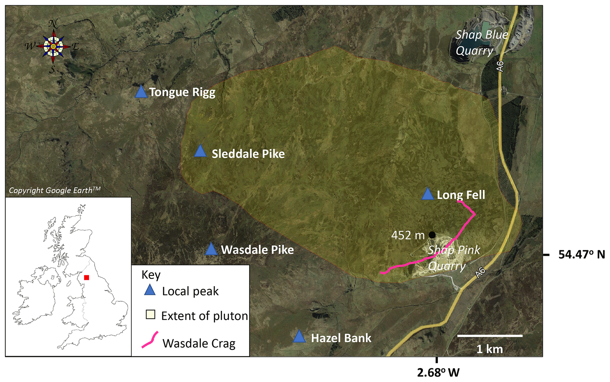
Figure 1Location of the Shap granite pluton relative to the A6 highway. The central portion of the ice-plucked outcrop (Wasdale Crag) has been destroyed by quarrying. Spot height elevation is metres above sea level. Base map is from © Google Earth. Approximate extent of the Shap granite pluton outcrop from the British Geological Survey (https://www.bgs.ac.uk/map-viewers/geoindex-onshore/, last access: 20 February 2024).
In terms of concentration, the dominant dispersal of Sg erratics during the early phase of the Dimlington Stadial (Stage I; ca. 29–25 ka BP; Merritt et al., 2019) was eastward (Carling et al., 2023) within sustained ice flow through the topographically controlled corridor of the Stainmore gap across the North Pennines hills (Fig. 2a). The plume extended as far as the east coast of England: a distance of more than 100 km (Fig. 3). Block size tends to diminish with distance, although examples of far-travelled large blocks occur sparingly (Carling et al., 2023). Due to shifting ice divides and competing ice dispersal centres (Evans et al., 2009; Merritt et al., 2019), subsequently two Sg plumes dispersed in southerly directions until, in the late stadial, erratics briefly were dispersed northwards from the vicinity of the pluton (Carling et al., 2013) in accord with the ice movements reported by Livingstone et al. (2012). These latter dispersal directions are not considered further herein. The focus is solely on those erratics for which the final transport vectors (direction and distance) are roughly due east, defining a simple linear direction over which changes in the nature of the erratic populations might be measured.
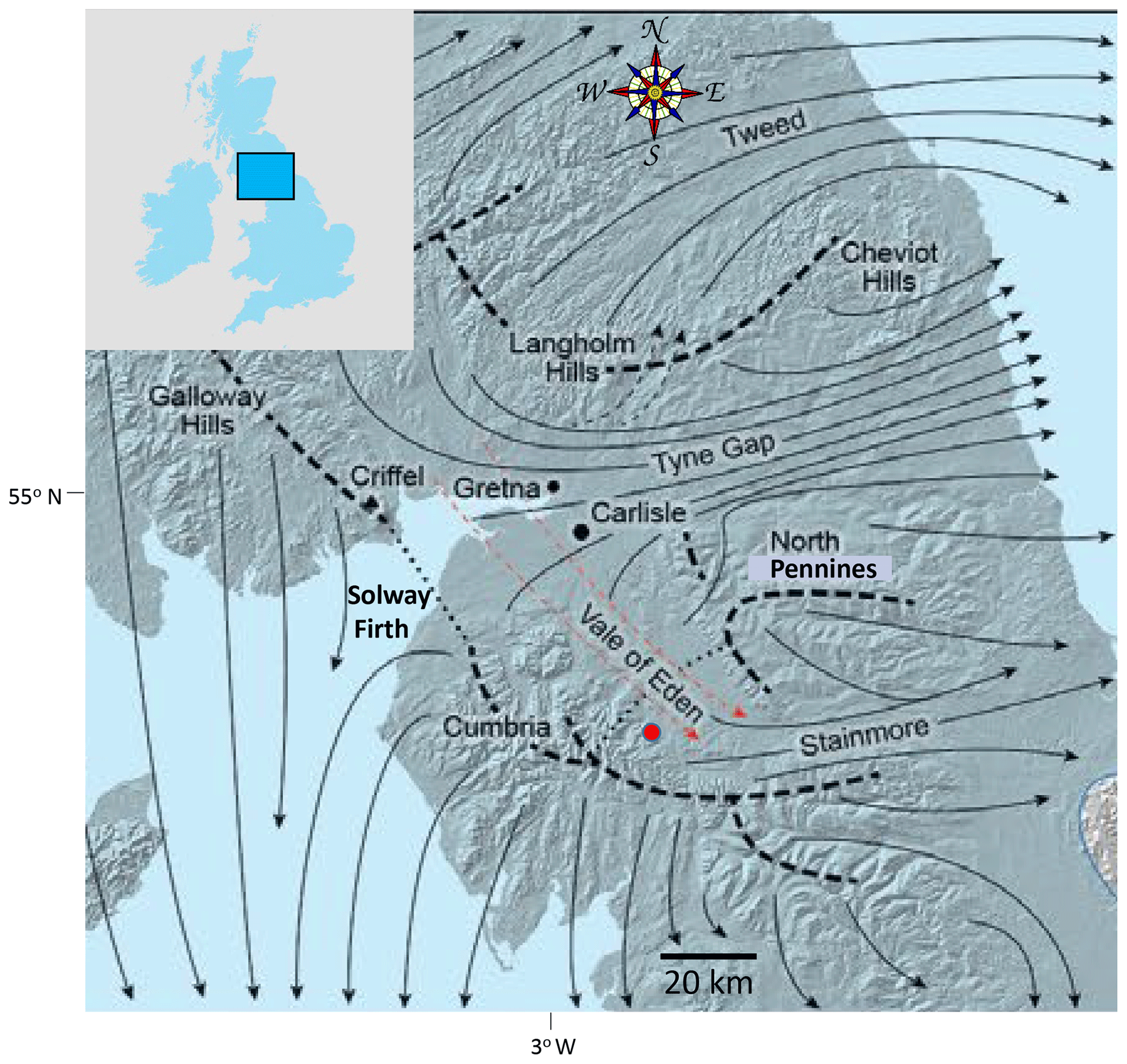
Figure 2Ice flow directions for Stage I (29–25 ka BP) of the last British–Irish ice sheet around the Solway Firth (from Merritt et al., 2019, reproduced with permission) in northern England (inset panel). Eastward ice flow through prominent topographic corridors occurs across the North Pennines. Broken and dotted black lines refer to ice divides. Black arrows indicate ice flow vectors (dotted red arrows indicate alternative ice flow scenarios). Topography from NEXTMap digital elevation data. Shap granite erratic plume dispersed to the east from the pluton (red dot) chiefly over Stainmore (see Fig. 3).
Less well understood than directions of travel and changes in concentration is the process of edge rounding and shape changes of Sg blocks that accompany size reduction. The granite is an ideal choice for study as the composition and texture are uniform (Grantham, 1928), mostly giving a massive, unlayered structure to individual blocks. Layering, such as found within sedimentary rocks, would add complexity to the study of shape evolution, which is avoided in this study. Hopkins (1849) commented briefly on the rounding of Sg blocks (density ∼ 2.61 t m−3) as size is reduced towards the east coast, yet such rapid changes in form are seemingly at odds with the high strength of the rock. The strength of Sg in compression exceeds 207 MPa (Holland, 1959; Day and Goudie, 1977; Goudie, 2006) such that the rock is considered “very strong” (British Standard Institution, 1981). Despite the rock strength, Hodgson (1870) remarked on how seemingly rapid rounding of granite might be aided by rock friability due to a high mica content associated primarily with biotite (Firman, 1953). Biotite is soft compared with the large phenocrysts of feldspars and quartz (Firman, 1953) that dominate the granite composition. Nevertheless, there has been no investigation of the changes in shape and rounding of Sg blocks with distance from the source, with very few granite blocks visually maintaining significant mass over tens of kilometres. A study of blocks exposed on the modern land surface, away from major watercourses, should reveal rock-wear processes associated with glacial transport as there have been negligible losses to Sg surfaces due to post-glacial subaerial weathering (Wager, 1944; Parsons and Lee, 2005). The few weathered examples of blocks exhibit phenocrysts standing proud (3–5 mm) of the matrix, as the mica is readily subject to chemical weathering if buried but the feldspars are not much altered (Wager, 1944). Consequently, a hypothesis was proposed: “Sg ice-transported blocks would display systematic changes in edge rounding and shape” with an aim “to demonstrate if edge rounding and shape coevolve with distance to the east from the pluton”.
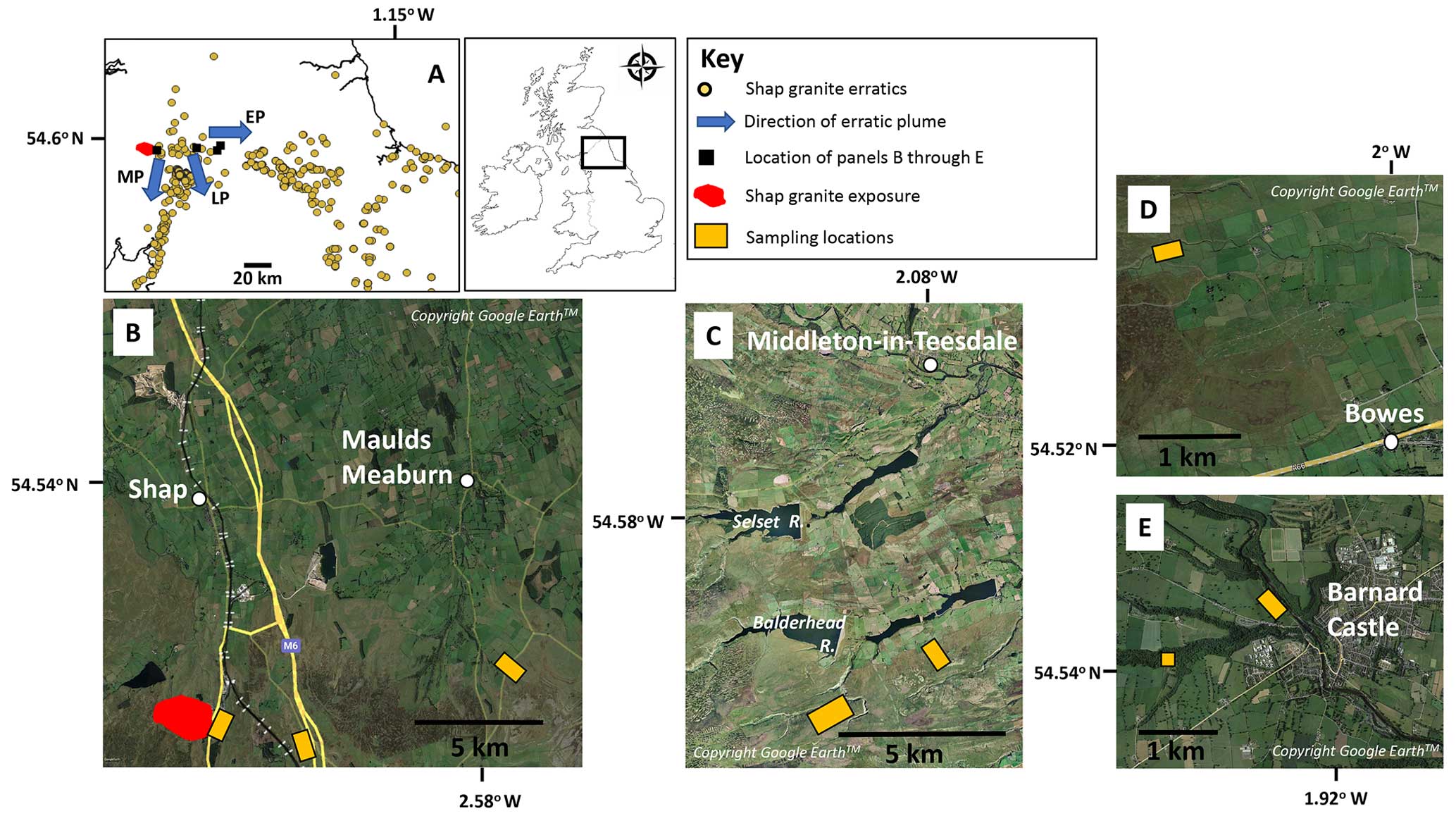
Figure 3(a) Spatial distribution of examples of Shap granite erratics within the study area, northern England (inset), showing the early easterly directed plume (EP) and the later southerly Mint and Lune plumes (MP and LP) relative to the source outcrop of Shap granite. Locations shown within panel (a) are indicative of the general sampling areas of (b) Wasdale Bridge, Haybanks, and Blasterfield; (c) upper Teesdale; (d) Levy Pool; and (e) Barnard Castle. See main text for details. Base maps copyright © Google Earth.
Shape (and size) changes in a Shap granite block occur due to three predominant processes which scale from affecting small areas of a block to larger areas:
-
abrasion, whereby grain-size fragments (e.g. phenocrysts) are ground off the block surface (Haldorsen, 1981; Benn and Evans, 2011) primarily by shear stresses associated with blocks moving across a bedrock or till surface in the direction of basal ice motion or by ice and till moving over stationary blocks lodged against the substratum – this process can result in distinct rounded surfaces on a block (Boulton, 1978; Hallet, 1979);
-
spallation, whereby flakes of rock are freed from the surface of the block (Olsen, 1983) due to externally derived and internally derived tensile deviatoric stresses in the rock, both imposed by the motion of the ice overburden, with the shear stresses acting on planes at less than the block scale (Li et al., 2018) – this process reduces block mass but results in localized scarred surfaces;
-
fracture (Buscarnera and Einav, 2021), whereby the “parent” block splits into substantial parts (often two; here referred to as “child” products). The propagating fissure ultimately may be due to compression loading, but, at the block surface, it is the result of a tensile stress (acting on a plane at block scale) flexing the stoss surface of a brittle block lying on a hard basal surface, leading to fissure development often transverse to the direction of basal ice motion (Morland and Boulton, 1975; Hallet, 1996; Benn and Evans, 2011, p. 264). The tensile strength of a rock is typically an order of magnitude less than the compressive strength (Li et al., 2018). This tripartite classification informed the Method section.
To address the hypothesis, the focus of the study is abrasion and fracture, but observations on spallation were obtained for completeness, with the latter results reported within Sect. S2.1 in the Supplement. There is justification from studies of bedrock outcrop erosion by basal ice that both the degree of abrasion of bedrock surfaces and the number of fracture events are related to time in transport (Cohen et al., 2006) and thus the distance erratics are moved.
Shap granite blocks were sampled along a west-to-east transect, starting from below Wasdale Crag. It was assumed that all the sampled blocks were from the same population subject to basal traction transport (vis. Boulton, 1978) for much of the transport histories, with the population being a coarser component of a subglacial traction till (sensu Evans et al., 2006) deposited during the waning of the easterly phase of ice motion (Fig. 3a) (Hallet, 1979). Blocks (L> ca. 1.0 m) were located by field walking. Locations sampled include Wasdale Old Bridge, Haybanks, Blasterfield, sites near Barnard Castle in Teesdale, and Levy Pool near Bowes (Table S1), which are 0.8, 3.5, 8.4, ca. 36, and ca. 41 km from the Wasdale Crag outcrop, respectively (Fig. 3). From preliminary site surveys, the sites selected were known to have sufficient erratics within defined areas for sampling. However, to obtain similar sample sizes, the areas searched for the final two locations necessarily increased as the surface density of blocks decreased eastwards. Examples of erratics were selected that were sitting on exposed bedrock or till surfaces so as not to be partially buried. Distance from the source outcrop is assumed to relate to time in transport.
At each location, edge and shape measurements as well as scar enumeration were made on 30 blocks as briefly described below; the full procedure is developed within the Supplement. The sample size was found to be sufficient (Daniel, 1999; Conroy, 2018) for the aims of the project, and, moreover, interpretation of data trends became possible once the sample size, n, reached 30 at each location. These data were supplemented by a regional shape data compendium (Carling et al., 2023). Changes in block size with distance from the pluton are not considered herein using field data, as a statistically significant sample size at each location would have to be prohibitively large to reflect the complete size range of blocks. Rather, block size changes are considered within a theoretical framework related to shape changes. Blocks are considered to be cuboids consisting of faces and edges.
In accord with (1) abrasion, edge rounding was measured after Wentworth (1923; Kirkbride, 1985). In brief, each of the three most tightly rounded edges on the visible portion of each block was defined by a chord (l), delimiting a segment of the block beneath each rounded edge, to give between 80 and 90 values for each location. Consideration of the height (h) of the segment in relation to the chord length constrains the radius (rc) of an inscribed circle beneath the rounded edge (see Fig. S2 in Sect. S1.4), the radius of which is a measure of the degree of rounding.
The radius of curvature is reduced as the chord length is reduced towards zero, and often a right-angle corner occurs when rc approaches 0. More rounded blocks have larger radii of curvature than less rounded blocks as the sizes of the inscribed circles increase as edges become less sharp. In a similar fashion, the edge rounding was measured for joints bounding in situ Shap granite blocks constituting the outcrop of Wasdale Crag. These latter data provide a baseline of the degree of edge rounding of blocks which have been subject to ice abrasion in place, but without subsequent transport.
To consider (3) shape changes by fracture, from initial field reconnaissance blocks close to the source often appear cubic, but polyhedrons occur sparingly – ranging from wedges to prismatoids. Further from the source more ellipsoidal forms are evident. Consequently, to obtain an indication of the shape of a cuboid or an ellipsoid block, the lengths of the three orthogonal axes, the long axis (L), medium axis (M), and short axis (S), were recorded in the field – polyhedrons were not sampled – to give ca. 30 values for each location. Consideration of the mechanics of shape changes also sheds light on the size reduction process with distance. Fracture within individual blocks is sometimes associated with joints and other block-scale planes of weakness. Yet, ice compressive force is the predominant mechanism for significant progressive change in shape for homogeneous granite blocks, inducing tensile fracture and block size reduction. Shape and size changes were examined either via a stochastic fracture model, applicable to fracture at right angles to either of the L, M, or S axes (Domokos et al., 2015) of ellipsoidal blocks or, in accord with the silver ratio model, applicable to cuboid blocks fracturing across the M axis alone (Buscarnera and Einav, 2021), as explained in the Results section. Shape indices are reported in the main text using the Zingg (1935) projection, whilst an example of a simple ternary diagram (Fig. S3, after Hofmann, 1994) is provided in Sect. S1.5.
3.1 Edge rounding
As is evident from the form of Eq. (1), rounding is a positive function of the square of the length of the chord of the segment, l, and an inverse function of the segment height, h (Fig. 4). As the inscribed radius values are obtained from both the values of l and h (Eq. 1), there is an element of covariance between the two axes in both Fig. 4a and b. However, plotting the data in this manner allows ready visualization of the trends of the radius data (rc) relative to the variation in the controlling parameters (l, h). Lower limits to data plotting positions occur in both panels equal to and rc=h, respectively.
The joint rounding on the pluton is less developed in comparison with the rounding of edges of blocks only 0.8 km away at Wasdale Old Bridge (Fig. 4). Although the range in heights of the segments is similar for both locations, the range in chord lengths for the pluton includes smaller values giving overall “sharper” edge profiles for the pluton joints in contrast to the Wasdale Old Bridge blocks. It is evident that any parent blocks newly entrained from the outcrop will exhibit both lightly rounded joint edges (glacially abraded when in situ) and sharp, fresh edges, the latter due to fracture upon release from the outcrop. However, although the initial lightly rounded edges can be further rounded with distance, fracture of entrained blocks introduces new sharp edges as detailed next.
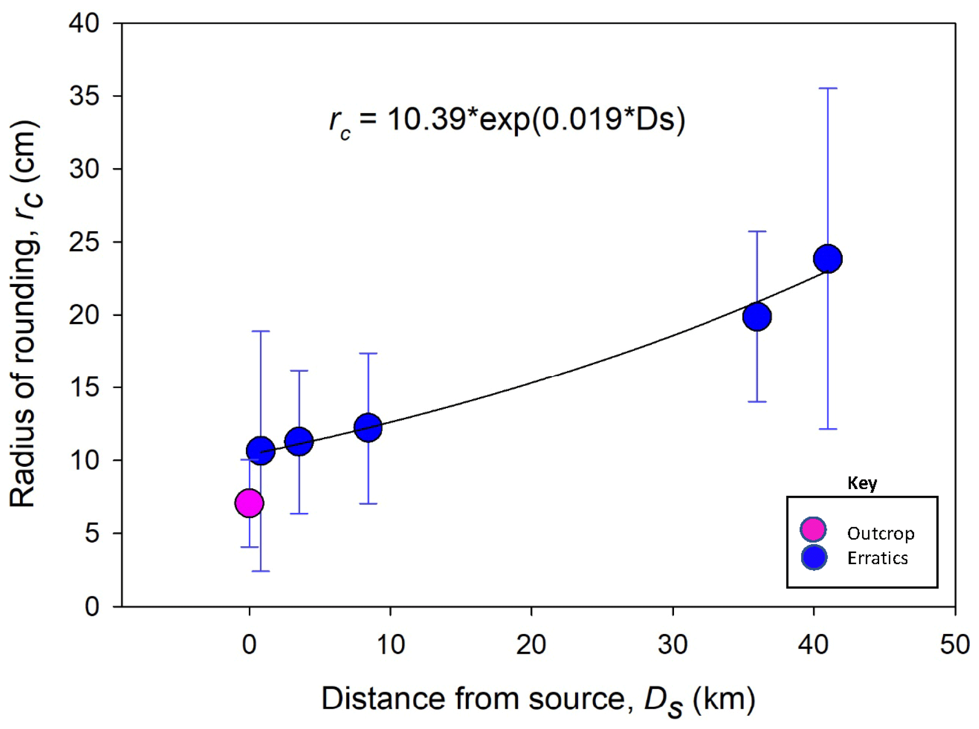
Although as distance increases larger radii are more frequent, small radii also occur at distance (Fig. 4). It is unlikely that small radii can survive abrasive transport over several tens of kilometres from the pluton; rather, repeated fracture introduces new sharp edges and thus new small radii to different generations of blocks. These new sharp edges begin to round far from the pluton. Although the plots of Fig. 4 are developed considering singular data points from many blocks, if the trends are considered to represent the rounding evolution that would occur for individual blocks, then the black arrows indicate the general direction of edge rounding evolution (i.e. Fig. 4a if h is constant and l is variable; Fig. 4b if l is constant and h is variable). The linear functions in Fig. 4b allow ready comparison between locations such that, for any value of h, the degree of edge rounding is more pronounced with distance from the pluton; specifically, the linear curves (green, blue, purple, and red) have increasing values of the constant (i.e. 1.71, 4.37, 4.69, and 5.53, respectively). Similar linear functions for values of l can be applied to Fig. 4a, but, for the sake of clarity, these curves are not plotted. The detail of edge rounding is considered within the Discussion section, as edge rounding of individual blocks is not a smooth function of distance from the source as might be inferred from the black arrows in Fig. 4 and from mean radius of edge rounding with distance from the outcrop (Fig. 5). The latter figure depicts an exponential increase in the mean radius of curvature with distance (Ds) from the source outcrop:
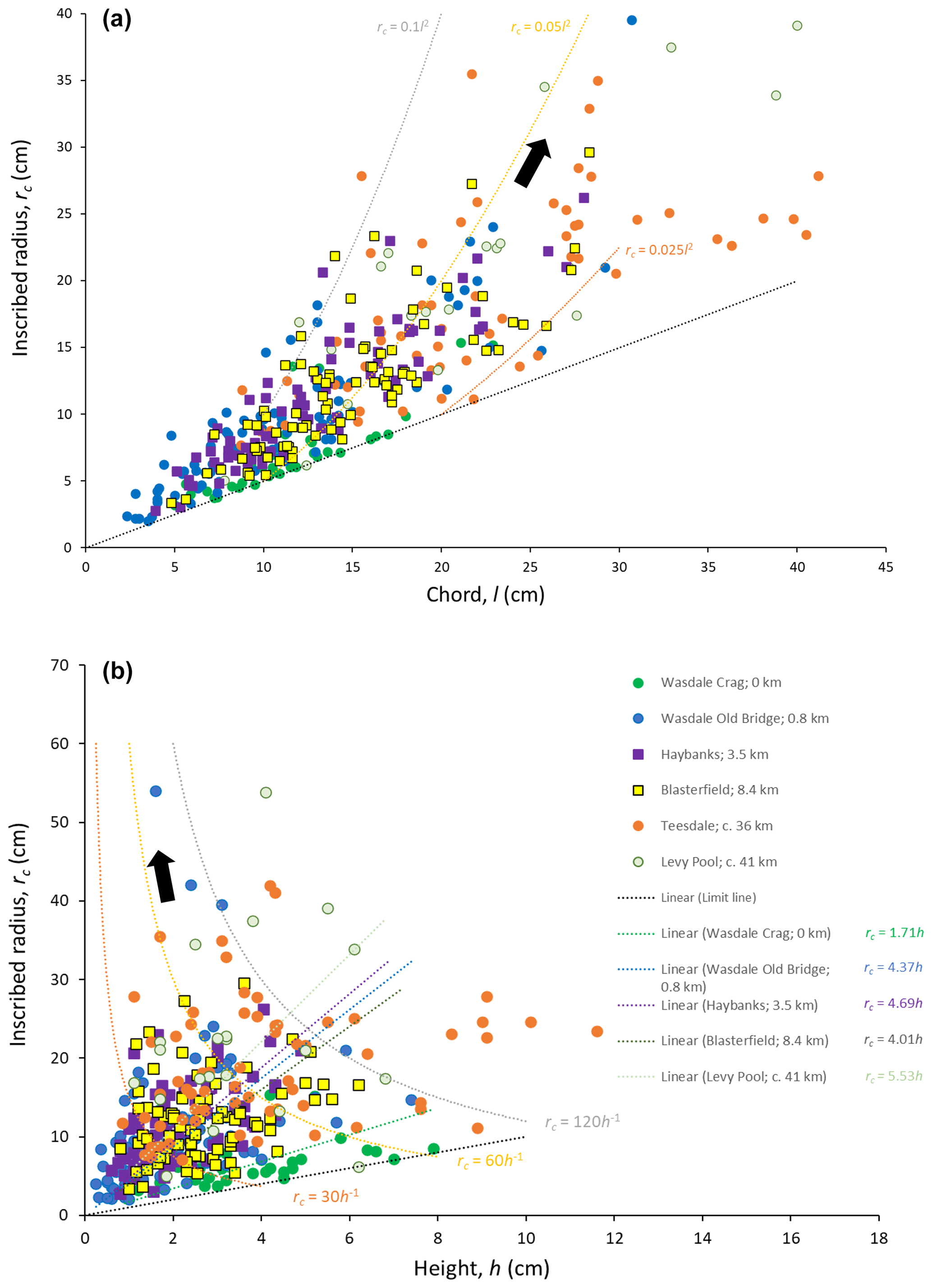
Figure 4Trends in the values of the inscribed radius as a function of (a) chord length and (b) segment height. Black arrows indicate the direction of travel of the hypothetical function for an individual block (see main text). Examples of hypothetical curves (brown, yellow, and grey) for the trends in individual clast evolution are given for both rc∝l2 and . The key to symbols in panel (b) also applies to panel (a).
3.2 Shape evolution
In the context of natural hexahedrons, the stochastic model of progressive fracture due to the stress of compression (Domokos et al., 2015) describes the generation of ellipsoids with the orthogonal axis length proportions 2.32 : 1.52 : 1 (Fig. 6a), whereas the silver ratio progressive fracture model (Buscarnera and Einav, 2021) describes the generation of cuboids with the edge length proportions : : 1, i.e. 1.59 : 1.26 : 1 (Fig. 7a). In the former model, a fracture plane is orthogonal to any of the three sides of a cuboid (enclosing the ellipsoid) and separates two pieces of equal mass. In the silver ratio model, a fracture plane occurs orthogonal to the current longest axis, separating two pieces of equal mass. In nature, deviation from these two models can occur such that shape self-similarity, in terms of axial ratios, is not necessarily maintained upon successive fracture events if the subsequent fracture is across an axis that differs from the previous fracture event. Fracture across the plane of the short axis was observed in nature (Fig. 6b). However, systematic fracture across the plane of the long axis (Fig. 6c) and across the medium axis (Figs. 6d, 7b) appeared predominant (vis. Benn, 1992) for the blocks observed in the field, in accord with both the stochastic and silver models. Given that most blocks rest with the short axis vertical, fracture across the L or M axes is consistent with known fracture mechanics, whereby the centre of an object is the location, under loading, of the maximum in the tensile stress and the consequent nucleation point for fracture (Hiramatsu and Oka, 1966; Shipway and Hutchings, 1993). From this point, a fracture line develops to the block edges (Man et al., 2018) transverse to the direction of tensile loading. For threshold values of static or dynamic loading, the rock eventually ruptures into two parts (Man et al., 2018). Thus, although a block on occasion might fracture across an axis at variance with the two models above, there is a tendency for blocks to evolve towards one or the other model. The system state attractors for these two models are shown in Fig. 8, wherein natural block shapes are considered. Importantly, compression and tensile fracture initially leads to uniquely defined anisotropic forms in both models, although isotropic forms () can occur in principle with progressive fracture.
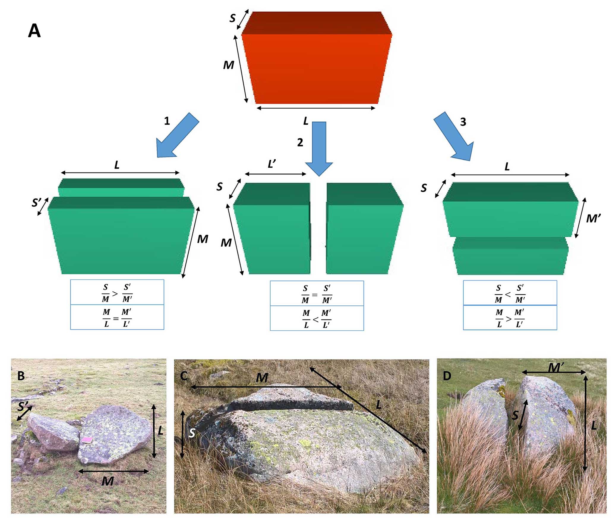
Figure 6(a) Schematic representation of the concept of the stochastic fracture model applied to a cuboid (enclosing an ellipsoid – see Fig. S1) subject to successive fracture given an assumed identical stress loading to the granite block at each fracture event. Fracture planes are orthogonal to a side and separate two pieces of equal mass. Shape self-similarity is not maintained upon successive fracture events. Three different fracture styles are possible within the model, labelled as 1, 2, and 3. (b) Example of a well-rounded block split along a fracture plane consistent with model 1. (c) Example of a well-rounded block split along a fracture plane consistent with model 2. (d) Example of a well-rounded block split along a fracture plane consistent with model 3. The long axes are foreshortened in panels (b–d).
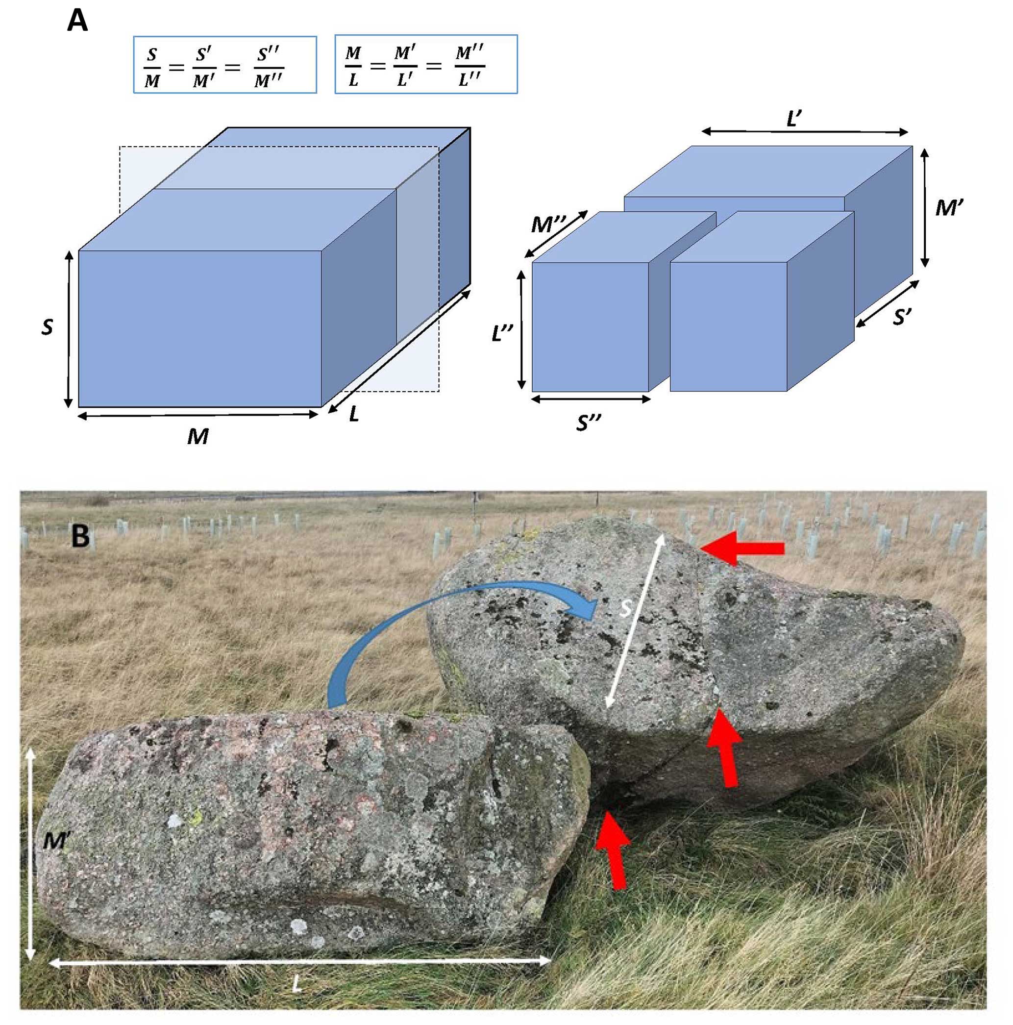
Figure 7(a) Schematic representation of the concept of the silver ratio model applied to a cuboid (see Fig. S1) subject to successive fracture given an assumed identical direction of stress loading to the granite block at each fracture event. Fracture planes are orthogonal to the current long axis. Shape self-similarity is more closely maintained (in contrast to Fig. 6) upon successive fracture events. (b) Example of silver ratio block. The block to the left is approximately the same size as the block to the right, and the lower surface (not seen) was originally on the top surface of the right-hand block with the exposed failure plane bisecting the M-axis alignment of the original parent block. The red arrows delineate a fracture plane aligned with the M axis of the right-hand block, which divides the right-hand block into two nearly equal halves.
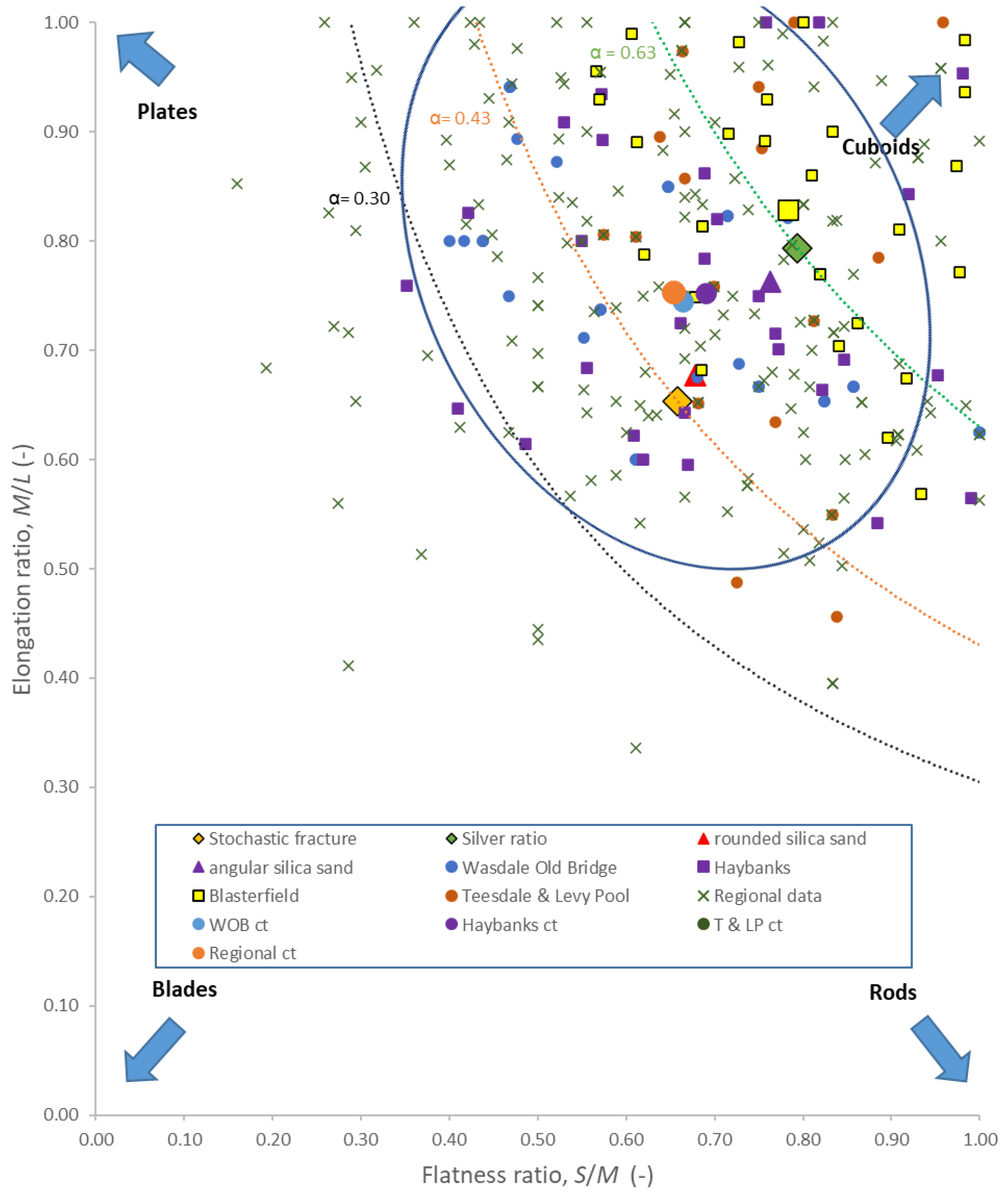
Figure 8The shape relationship for blocks in terms of the Zingg (1935) ratios. The system state attractors for stochastic fracture (gold diamond) and the silver ratio (green diamond) are shown as larger symbols, as are the central tendency shapes for mechanically crushed silica sand grains that were initial sub-rounded or angular (Seo et al., 2021). The central tendency (ct) for each sampled location, defined by the mean values, is shown as larger symbols. Curves represent the trend in values of and for constant values of . The ct symbols represent the central tendency of each population. The oval is the 95 % contour after Oakey et al. (2005).
Within Fig. 8, the Zingg ratios ( and ) for the sampled locations are plotted together with a data set for the broader region (Regional data). Within Fig. 8, completely equant (isotropic) forms are absent and plate-like forms survive more readily than rods. Nonetheless, the central tendency of block shape within the regional data is 0.65 and M/L= 0.75, i.e. roughly midway between the system state attractor for stochastic fracture and the silver ratio attractor. Lines of constant equal aspect ratios () are shown for the silver ratio model (α= 0.63) and for the stochastic fracture model (α= 0.43). Seo et al. (2021) showed that for homogeneous silica grains, fracture depended on initial particle form (Fig. 8) with angular grains tending towards the silver ratio whilst rounded grains tended towards stochastic fracture. If the fracture process is scale-invariant, then the size differences between silica grains and the Shap blocks can be ignored, and one would expect the Shap granite (a largely homogeneous lithology) to migrate across the diagram from silver to stochastic fracture as cubic blocks become progressively more rounded and ellipsoidal. Blocks deviating from either model (either too long or flat, e.g. approaching α= 0.30) will tend to fracture and migrate back towards α= 0.43, as is especially evident in Fig. S6b within Sect. S2.2. The central tendencies of the regional data and each of the sampled locations are closely grouped between the central tendencies of the silver and stochastic fracture models. The exception is the Blasterfield location, which lies closer to the silver ratio, but with increased distance of transport, Teesdale and Levy Pool blocks are in accord with stochastic fracture. Thus, it is evident that block fracture fluctuates between each model, with a trend toward constant equal aspect ratios close to α= 0.50 (not plotted in Fig. 8).
Although Fig. 8 provides an impression of the spread of block shapes around a central tendency there is no clear impression of the actual shape evolution as possible representative shapes can only be selected arbitrarily from the data clouds. Further, only the cube (or sphere) limit point (e.g. 1, 1 in Fig. 8) is real. Limit points for rods and plates exist only through mathematical definition because as the rod and plate limit points are approached, rods become infinitely long and plates infinitely thin. Thus, representative shapes need to be selected objectively. To solve this problem the procedure of Oakey et al. (2005) was utilized to define representative shapes that define the 95 % contour around the central tendency of the regional data, represented by the blue oval in Fig. 8. With reference to the position of the 95 % contour in the blade quadrant, curve α= 0.30 is selected to demarcate a lower bound for common block ratios, with a few plate-like or rod-like blocks occurring in the lower portion of the diagram.
3.3 Size evolution
The size distribution of the Shap granite blocks with distance from the pluton source has not received detailed attention, although Carling et al. (2023) provide some general observations suggesting there is size reduction with distance. In this study, the sample sizes were insufficient to demonstrate the reduction in block size expected with distance from the source outcrop. However, controls on size reduction are evident. Specifically, blocks greater than L= 4 m are rare (Carling et al., 2023), the size being controlled by the close joint spacing of the granite at source (Firman, 1953). With few exceptions, large blocks (L> 3.0 m) do not occur beyond 7 km from the pluton, at which point medium blocks (2.5 > L>1.5 m) become scarce, with small blocks ( m) and cobble-sized material dominating with further dispersal (Carling et al., 2023). These observations indicate that there was a control on the upper size of blocks entrained from the pluton and that fracture rapidly reduced block size, inducing a crude size reduction down-plume within just a few kilometres. This process was accompanied by local deposition of abrasion and spallation debris as components of a subglacial traction till. Nevertheless, the fracture mechanics that control block shape inevitably control size evolution (Figs. 6 and 7). For example, fracturing a parent cube with 4 m long edges and its progeny across the L axis, only six sequent fracture divisions are required to produce a 1 m cube, as will be demonstrated in the Discussion section.
The initial hypothesis proposed that Sg ice-transported blocks would display changes in edge rounding and shape with distance to the east from the pluton. As shown in the Results section and elaborated below, edge rounding does change with distance but block shape is conservative.
Space–time substitution is an underlying tenant of this study in that the size and shape characteristics of multiple individual blocks (an erratic plume), dispersing across the landscape, can reflect the evolution of a single erratic block through time along the same general spatial trajectory. An adequate number of sampled blocks is required for this analogy to hold because perturbations to the population of erratics can occur during dispersal. For example, blocks can have been introduced to the W–E trajectory of the study plume by N–S ice movements reworking blocks previously deposited outside the eastern-directed plume during periods of time after the main W–E ice flow. Also, for the purposes of determining transport distance, a zero x-axis origin has been assumed to be the most easterly outcrop of the pluton at Wasdale Crag. However, some blocks might have been sourced up to a few kilometres to the west of Wasdale Crag. Despite these potential perturbations, which include a small degree of subaerial weathering, the sample sizes are sufficient to clearly demonstrate systematic change in edge rounding due to ice transport as well as block shape evolution. Finally, edge rounding and shape are reset to a degree for the children each time a parent block fractures, so the process of rounding and shape adjustment is not a smooth function of distance from the outcrop, as is explained below.
4.1 A conceptual model of block edge rounding
It should be acknowledged that this study has not considered abrasion of the faces of blocks but has focused on the edges which tend to abrade and round more rapidly than the associated faces (Boulton, 1974). The edges of blocks still within the outcrop are sharp, although some are subject to a slight degree of rounding in place (Fig. 4) from glacial wear, as well as a little post-glacial subaerial weathering. Detached blocks close to the outcrop also tend to exhibit slightly ice-rounded edges, with sharply angled joint planes characterizing the faces due to fracture release of the block from the outcrop. The increase in edge rounding with distance confirms the initial hypothesis.
Block edge rounding is initially constrained by the hardness of the Shap granite and the way it fractures when first entrained at the outcrop. The absence of significant edge rounding at the outcrop indicates that blocks were continually entrained until the imposed stresses fell below that required to quarry further blocks. Otherwise, edge rounding of entrained blocks is associated with basal traction transport (Boulton, 1978; Hallet, 1979). Although the compressive strength of granite is high, the tensile strength is an order of magnitude lower, possibly as low as 4 % of the compressive strength, i.e. 8 MPa (Anikoh et al., 2015; Demirdag et al., 2018; Engineering ToolBox, 2008; Yu et al., 2018). Thus, where compression is translated into flexure, the propensity of the block to elongate across the axis of flexure readily leads to fracture of the brittle granite. This condition means that many blocks close to the source initially exhibited nearly right-angle edges (Fig. 4). Given this geometric constraint, radii of edge curvature are inevitably small initially, approaching the limit and rc=h, and increase with distance from the outcrop due to abrasion. However, fracture away from the outcrop introduces new sharp edges (Figs. 4 and 8) such that larger radii characterizing an individual edge-rounded block just before fracture are augmented by smaller radii. This change is reflected in the scatter of radii values found with increased distance from the outcrop (Fig. 4). However, as block size is reduced, a condition is approached whereby the population of blocks is increasingly made up of those which resist fracturing (see the “Block size controls” section), which should allow edge rounding to become more persistent and thus more pronounced with distance. This condition may be approached in the case of the examples from Teesdale (Fig. 4a) where it is evident that short chords become fewer with distance as larger values of rc begin to dominate the population. As blocks in transport can reorient within the ice flow, edge rounding has no effect on block shape, given the shape definition herein. However, if blocks are not free to reorient, a case not considered herein, the form of blocks can be significantly affected by abrasion in place (Boulton, 1974; Hallet, 1979).
Although a positive exponential function (Eq. 2) describes the increase in the mean radius of edge rounding with distance from the source outcrop (Fig. 5), the function must eventually transition to a negative function as abraded smaller blocks are inevitably characterized by smaller radii of curvature. This latter condition was not recorded within the current study, and sampling at greater distances from the source would be required to determine if this transition occurs. A block (e.g. 1 m cube) subject to edge rounding equally on all 12 edges, as per Eq. (2), would have lost about 4 % of its mass after 10 km and 9 % after 40 km; so, in contrast, fracturing into two self-similar parts whereby 50 % of mass is lost is more significant than edge rounding in terms of mass loss per block. The greater significance of fracture is consistent with studies of ice erosion by quarrying and ripping versus abrasion of basal bedrock surfaces (see references in Cohen et al., 2006; Glasser et al., 2020; Hall et al., 2021).
Rounding of individual blocks is not a steady process, as is evident from the data scatter in Fig. 4 and further illustrated in the following section. The process whereby the percentages of edges of different generations are rounding with distance or time is shown schematically in Fig. 9a, wherein there are initially no more than 12 slightly rounded edges to a cube block newly released from the outcrop (see Sect. S1.6 and Fig. S4 for details of the model). The model is simple but demonstrates the complexity in edge rounding that must accompany successive fracturing of blocks. Fracturing the blocks successively across the L axis introduces new generations of fracture edges (sequent fractures – Fig. 9b) at the same time as reducing the number of edges on each new block related to earlier fracture events (see Sect. S1.6 for further details). As the number of progeny blocks increases exponentially for each fracture event (Fig. 9c) and each sibling can be further dissected along a choice of one, two, or three M axes depending on block shape, a diagram including all fracture progeny introduces unreasonable complexity, obscuring the key details. In Fig. 9a and b, for clarity, only one block is followed through one to six sequent fractures, which reduces the number of data points for plotting to a manageable number. The key point to illustrate is that the initial parent block must be fractured five times for one of the ensuing progenies to have lost all the initial 12 edges of the parent. The total number of initial parent edges is relatively persistent because there are 12 edges to begin with (Fig. 9). Contrarily, only four new edges (Fig. 9a) per block are produced on each fracture event. Thus, in contrast to the curve for the initial parent edges, the first fracture edges can be lost in as little as four fracture events depending on which sibling block is considered. The second fracture edges are lost by a total of five fracture events and so on as more fractures occur, adding new fracture edges. Relaxing the model to allow fracture across either the M or S axis (see Sect. S1.6) only adds one or two fracture events to the process of edge extinctions. Thus, by introducing new edges at each fracture event, rounding of the block with distance or time is not a steady progression, with well-rounded edges being lost as blocks are split at the same time as new immature edges are added to a population of sub-mature edges. The model may not apply beyond some undetermined number of fracture events if there is a critical minimum block size that is less susceptible to fracture (as was noted above) and rounding can then become pronounced. Nonetheless, this model explains the presence of a “continuum” from well-rounded edges to less well-rounded edges on many individual blocks. The issue as to whether there is a minimum block size is considered in the next section.
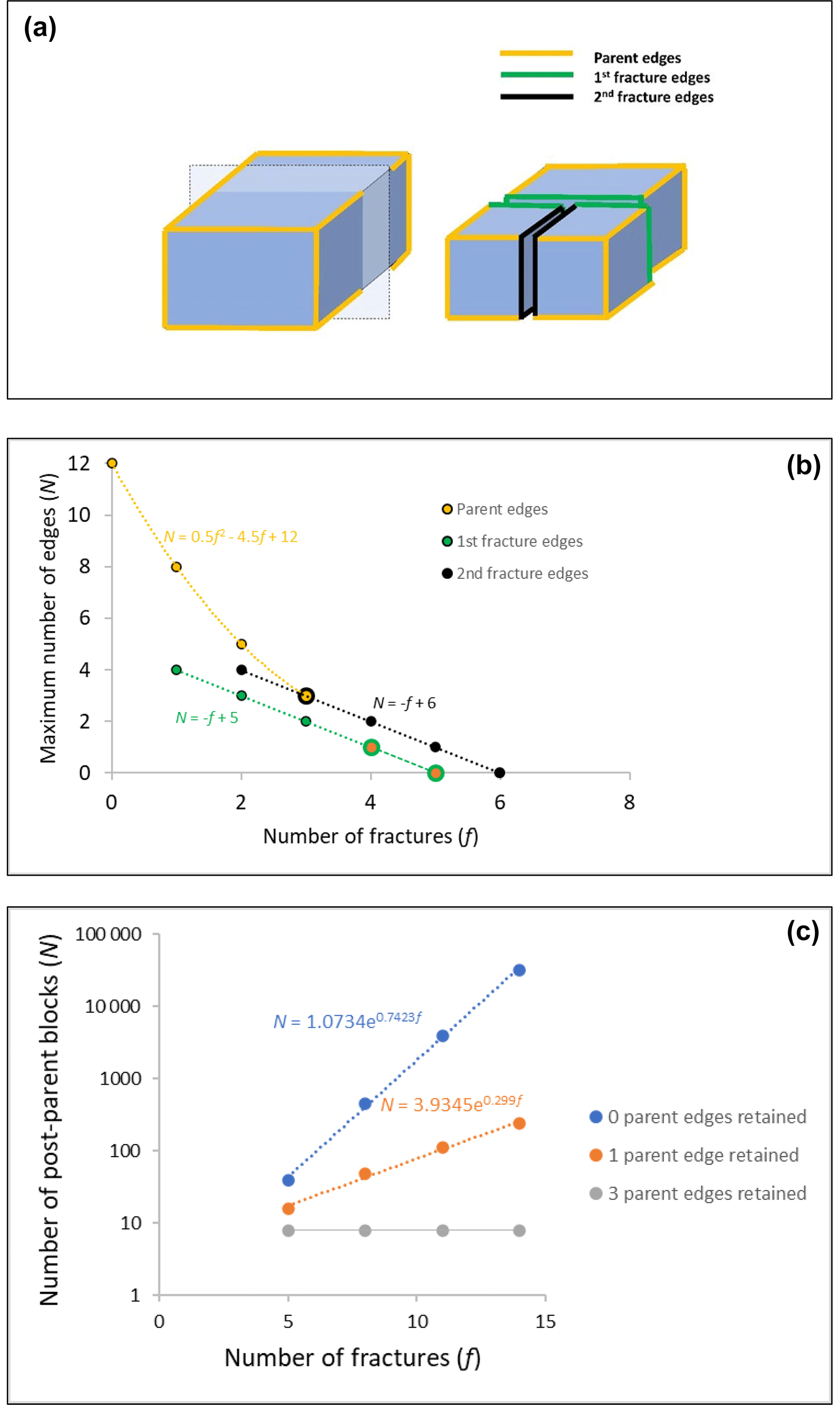
Figure 9(a) A regular block released from the outcrop has 12 initial edges (parent edges) all equally rounded. Fracturing the block at right angles introduces four new edges (first fracture edges) to each of two sibling blocks, the edges of which are younger than the initial edges. A further fracture across the L axis is indicated by second fracture edges. (b) The maximum number of edges of each generation on a block as a function of the number of fracture events, with only the parent edges and those edges related to the first two fracture events plotted. (c) The total number of blocks created at each fracture event which retain zero, one, or three of the original parent edges.
The significant increase in the mean radius of edge rounding with distance from outcrop (Fig. 5) indicates that the blocks were transported within a mobile concentration of basal debris, in frequent block-to-block contact, and in contact with the bedrock, leading to abrasion before being deposited within a subglacial traction till (Hallet, 1979). If the distance travelled towards the east is not the controlling factor, then the high degree of edge rounding may be due to prolonged temporal transport, with some material moving east, south, and then north again, extending the transport distances. However, compatible with studies showing block modification after distances of only 0.4 km (Humlum, 1985; Lliboutry, 1994; MacGregor et al., 2009), an alternative main explanation is preferred for the easterly edge rounding trend. Although Sg is mechanically strong in compression (Goudie, 2006) it is susceptible to abrasion and tensile fracture for the following reason. The blocks contain large pink phenocrysts set within a matrix of smaller mineral crystals. The large pink crystals are orthoclase feldspar (Moh hardness 6–6.5). The other common minerals are glassy quartz (Moh hardness 7), white plagioclase feldspar (Moh hardness 6), and black biotite mica (Moh hardness 2.5–3) (Caunt, 1986). Thus, the granular composition of the granite with harder crystals adjacent to a soft mineral may aid rapid rounding by abrasion and facilitate tensile fracture during glacial transport.
4.2 Block shape controls
Block shape is dependent on the initial controls exhibited (1) at the outcrop of origin and (2) in the subsequent transport history.
-
The primary control is the intersection of sub-vertical joints (Firman, 1953) in the granite with horizontal expansion joint planes caused by unloading (Jahns, 1943). Horizontal joints are largely due to glacio-isostatic rebound and surface erosion (Westaway, 2009), leading to the release of the residual stresses accumulated at depth (Berger and Pitcher, 1970). The resultant blocks initially tend to be cubic. Where blocks lie within a few metres from the parent outcrop, the block faces tend to be planar, although curved fractured surfaces occur occasionally, as do conchoidal fracture hollows on otherwise planar surfaces. Curved fracture surfaces tend to occur in homogeneous granite due to pressure unloading (Wang et al., 2022), which will have occurred as ice erosion reduced the overburden. Such joint-defined blocks within an outcrop are readily entrained by moving ice (Matthes, 1930; Morland and Boulton, 1975).
-
Although inhomogeneous blocks in traction may be envisaged as breaking down into multiple fragments at each compressive event (Boulton, 1978), the largely homogeneous nature of the Sg lithology leads to simple tensile fracturing at each breakage event, whereby subsequent generations of blocks exhibit shapes largely similar to the parent forms. Thus, there is a tendency for equant blocks to persist through time and distance due to the tensile stresses associated with flexure across the stoss surfaces, reducing block mass in accord with either the silver model or the stochastic model. This trend is indicated by the fact that stronger plate-like blocks occur less frequently away from the pluton in contrast to the general absence at distance of the weaker rod-like blocks. Thus, cuboids progress to form both cubes and cuboids such that the initial hypothesis is rejected.
4.3 Block size controls
Block size is dependent on the initial controls exhibited (1) at the outcrop of origin and (2) in the subsequent transport history.
-
The primary control is the presence of the frequent, well-developed joint planes within the pluton (Firman, 1953; Caunt, 1986) which tend to define and delimit the range of the initial block sizes from ca. 0.5 to 4 m. Fault planes are of sufficient rarity to be ignored. Joints are largely orthogonal, i.e. sub-vertical and nearly horizontal, but oblique joints also occur.
-
Once in ice transport, other controls on block disintegration may pertain. In the present case, larger blocks close to the outcrop (< 0.8 km) often exhibit one (or more) intact or partially opened failure plane(s) inherited from the outcrop structure. More commonly, with distance from the outcrop (> 0.8 km), the planes of failure within individual blocks represent the directions of compressive and tensile forces exerted by the ice on the blocks (and thus bear no relationship to block structure or composition), as appears to be the case where failure planes are aligned with the L or M axes. Fracture occurred when the effective tensile stress exceeded the yield strength of the blocks. Glacial unloading, and subsequent stress release, may also introduce planes of weakness within transported blocks. Adopting the stochastic fracture model or the silver ratio model for block shape changes indicates that block volume effectively halves at each fracture event with consequent reduction in block size. This conclusion has implications for the fractal evolution of erratic size distributions which, for brevity, cannot be addressed within this paper.
Other small-scale planes of weakness can be attributed to spatial variations in the primary mineral composition (Grantham, 1928; Parsons and Lee, 2005), leading to textural and grain-size variations, which can be visible rarely as parallel lineaments, and later hydrothermal alteration also induced compositional and hence structural variations (Caunt, 1986). These weaknesses lead to loss of small blocks and flakes from the larger parent blocks (see Fig. S5 in Sect. S2.1) through spallation rather than fracture. Spallation may be related to the state of stress within a deforming till layer (Hooke and Iverson, 1995) rather than the tensile stress on the stoss side of a block which accounts for block fracture.
4.4 General considerations
A significant question is whether flowing ice can generate significant stress to fracture the granite blocks. If the thickness of the deforming ice–till layer at the basal boundary is small relative to the size of the boulder, then the compressive force is likely to dominate. However, if the reverse applies then the tensile force will likely dominate. Herein, given that there is no information as to the thickness of the deforming layer, the distinction is not considered because, in most cases, blocks will fracture at a lower stress due to tension in contrast to compression. In a consideration of similar situations, emphasis was placed on the compressive strengths of blocks (Boulton, 1978) relative to the normal stresses due to a static ice load above a block. In the present examples, the tensile strength of the stoss side of a block resisting flexure is more relevant for brittle fracture and for granite can be as low as 8 MPa, which is a tensile stress readily applied by a modest (ca. 100 m thick) yet dynamic ice cover (Hallet, 1996). The distribution of compressive and tensile forces over the stoss side of a block adjacent to the bedrock at the base of an ice mass will be complex and variable through space and time (Hallet, 1979; Morland and Boulton, 1975; Ficker et al., 1980; Cohen et al., 2005). Yet, a simple example below outlines the principles within the context of Shap granite erratics. Although a more complex and complete appreciation of the stress environment of a boulder would be preferred, a simple force balance is utilized instead. Simplicity is dictated by the absence of data to inform a more complex model.
Setting the tensile stress at failure to 8 MPa and treating the rectangular block as subject to a critical average driving force (τc) (Benn and Evans, 2011, p. 114) due to ice flow, transverse and longitudinal shear stresses arise of equal magnitude. Setting the fracture focus at half the block width in the direction of loading, neglecting any water pressure variations (Cohen et al., 2006) and deformation within a basal till (Hooke and Iverson, 1995), and imposing the driving stress transverse to the fracture plane, as little as 180 m thickness (H) of flowing glacial ice with an ice surface slope (β) of 1.5° would be sufficient to induce fracture in the block:
where ρi is the density of glacial ice and g is the acceleration due to gravity. The value of H= 180 m pertains for a rectangular block with a surface area (A) defined by L= 2 m and M= 2 m (see Sect. S1.7). The effective instantaneous stress might be greater than as given by Eq. (3) (Hooke and Iverson, 1995) but for a block with L= 3 m, M= 1 m with the long axis transverse to the ice flow the shear force maximum might be achieved with only 130 m of ice cover (see Sect. S1.7). To the east of the pluton the last British ice sheet was several hundred metres thick at ca. 25–22 ka BP (Evans et al., 2009) such that blocks would readily fracture during full-glacial warm-based conditions where ice is flowing, as well as after the Last Glacial Maximum when ice was thinning.
The smallest block sizes (L< ca. 1.0 m) present in the field were not considered, which means that the sampled population was truncated at the finer end. Nevertheless, although in some rock types a lower limit to block strength may be related to a minimum structural block size (Dreimanis and Vagners, 1971; Lim et al., 2004; Domokos et al., 2015), this is unlikely to pertain to granite which breaks down to grus at the scale of the phenocrysts. Nonetheless, fracture and surface wear to an initial block population tend to result in the observed block population consisting of blocks strongly resistant to further comminution (Moss, 1972; Tavares and King, 1998; Larson and Mooers, 2004; Pfeiffer et al., 2022), which, in principle, enables some blocks to survive transport adjacent to the sole of the ice for great distances before being deposited during the waning phase of the easterly directed ice stream (Hallet, 1979). Thus, although there may be no lower effective block size, a statistical increase in resistance to fracture of the block population with distance is likely evident as witnessed by the increased rounding seen in the Teesdale population. The occasional far-travelled large block, as noted in the Introduction, might be explained as being a statistically stronger example, in contrast to the remainder of the population. Alternatively, large blocks can be cushioned within the till body by smaller particles (Einav, 2007), thus avoiding fracture, or they can be transported englacially, rather than basally, and consequently not subject to protracted abrasion and significant compression whilst in traction. However, englacial blocks are more likely to be angular (Shilts, 1976; Boulton, 1978) and might retain rugose faces.
Thus, although the reduction in plume parameters values, such as block size and concentration, are commonly viewed as exponential functions of distance from the source (Shilts, 1976), such models (e.g. Fig. 5) consider the sampled population as a whole and the inferences derived may not apply to the transport history of individual blocks. Certainly, the reduction in edge rounding for individual blocks is irregular with distance.
The hypothesis that granite blocks would display an increase in edge rounding with distance from the source outcrop is confirmed, whilst the hypothesis that shape would evolve with distance is refuted. Although the increase in the mean radius of edge rounding for the whole block population increases exponentially with distance, edge rounding on individual blocks is an irregular function mediated by block fracture mechanics, as block size is reduced (with shapes fluctuating between cuboids, slabs, and rods) with distance and new sharp edges are provided to partially edge-rounded blocks. Thus, edge rounding and shape coevolve as block size is reduced. Fracture transverse to block orientation is in accord with the application of tensile stress, which controls the process by which block form is conserved as block size is reduced. Consideration of the orientation of the tensile fractures on blocks in the field might be used to approximate the direction of ice flow at the time of fracture.
Overall, the results indicate that edge rounding is unlikely to be advanced if blocks continue to fracture. Well-rounded blocks must represent blocks that have resisted splitting. In the case of exceptionally large, rounded blocks, the rock mass likely is unusually homogeneous, lacking potential fracture lines. However, smaller blocks are less likely to contain potential fracture lines, so fracture should become less prevalent as blocks are reduced in size, which then promotes edge rounding.
Future work should consider developing mathematical models that represent the function of edge rounding as predicated by a model (e.g. silver ratio) describing block size reduction. Similar studies considering other lithologies (e.g. stratified sedimentary rocks) would likely find different shape evolution patterns in contrast to the cuboid central tendency displayed by the homogeneous granite, with concomitant implications for edge rounding trends with time and distance.
Basic data are available upon reasonable request from the author.
The supplement related to this article is available online at: https://doi.org/10.5194/esurf-12-381-2024-supplement.
The author has declared that there are no competing interests.
Publisher's note: Copernicus Publications remains neutral with regard to jurisdictional claims made in the text, published maps, institutional affiliations, or any other geographical representation in this paper. While Copernicus Publications makes every effort to include appropriate place names, the final responsibility lies with the authors.
This article is part of the special issue “Icy landscapes of the past”. It is not associated with a conference.
Emma Armstrong (Armstrongs Group) is thanked for access to the Shap (Pink) Quarry. Leslie Knight and David Evans (Durham University) provided information on the location of Shap granite erratics in Teesdale and near Levy Pool. Leslie Knight provided the base image for Fig. 3a. Two anonymous referees and the editor, Arjen Stroeven, are thanked for their commentaries, which led to improved presentation of the final results.
This paper was edited by Neil Glasser and reviewed by two anonymous referees.
Anikoh, G. A., Adesida, P. A., and Afolabi, O. C.: Investigation of physical and mechanical properties of selected rock types in Kogi State using hardness tests, Journal of Mining World Express, 4, 37–51, https://doi.org/10.14355/mwe.2015.04.004, 2015.
Benn, D. I.: The genesis and significance of “Hummocky Moraine”: Evidence form the Isle of Skye, Scotland, Quaternary Sci. Rev., 11, 781–799, https://doi.org/10.1016/0277-3791(92)90083-K, 1992.
Benn, D. I. and Evans, D. J. A.: Glaciers and Glaciation, Hodder, London, 802 pp., https://doi.org/10.1111/j.1502-3885.2011.00212.x, 2011.
Berger, A. R. and Pitcher, W. S.: Structures in granitic rocks: A commentary and a critique on granite tectonics, Proceedings of the Geological Association of London, 81, 441–461, https://doi.org/10.1016/S0016-7878(70)80006-2, 1970.
Bouchard, M. A. and Salonen, V.-P.: Block transport in shield areas, Glacial Indicator Trains, edited by: Kujansuu, R. and Saarnisto, M., Balkema, Rotterdam, 87–107, ISBN 9781003079415, 1990.
Boulton, G. S.: Processes and patterns of glacial erosion, in: Glacial Geomorphology, edited by: Coates, D. R. and Binghamton, N. Y., State University of New York, Publications in Geomorphology, 41–87, ISBN 9789401164931, 1974.
Boulton, G. S.: Boulder shapes and grain-size distributions of debris as indicators of transport paths through a glacier and till genesis, Sedimentology, 25, 773–799, https://doi.org/10.1111/J.1365-3091.1978.TB00329.X, 1978.
British Standard Institution: Code of Practice for Site Investigations, BS 5930 HMSO, London, https://www.bsigroup.com/ (last access: 20 February 2024), 1981.
Buscarnera, G. and Einav, I.: The mechanics of brittle granular materials with coevolving grain size and shape, P. R. Soc. A, 477, 20201005, https://doi.org/10.1098/rspa.2020.1005, 2021.
Carling, P. A., Su, T., and Meshkova, L.: Distribution of Devensian glacial erratics and related evidence elucidate complex ice flow changes across a former ice divide: Northern England, P. Geologist. Assoc., 134, 139–165, https://doi.org/10.1016/j.pgeola.2023.01.002, 2023.
Caunt, S. L.: Igneous and Metamorphic Processes in the Shap Granite and its Aureole, unpublished PhD thesis, University of Leeds, 337 pp., https://etheses.whiterose.ac.uk/522/ (last access: 20 February 2024), 1986.
Chiverrell, R. C. and Thomas, G. S. P.: Extent and timing of the last glacial maximum (LGM) in Britain and Ireland: a review, J. Quaternary Sci., 25, 535–549, https://doi.org/10.1002/jqs.1404, 2010.
Clark, C. D., Ely, J. C., Hindmarsh, R. C. A., Bradley, S., Ignéczi, A., Fabel, D., Ó Cofaigh, C., Chiverrell, R. C., Scourse, J., Benetti, S., Bradwell, T., Evans, D. J. A., Roberts, D. H., Burke, M., Callard, S. L., Medialdea, A., Saher, M., Small, D., Smedley, R. K., Gasson, E., Gregoire, L., Gandy, N., Hughes, A. L. C., Ballantyne, C., Bateman, M. D., Bigg, G. R., Doole, J., Dove, D., Duller, G. A. T., Jenkins, G. T. H., Livingstone, S. L., McCarron, S., Moreton, S., Pollard, D., Praeg, D., Sejrup, H. P., van Landeghem, K. J. J., and Wilson, P.: Growth and retreat of the last British–Irish Ice Sheet, 31 000 to 15 000 years ago: the BRITICE-CHRONOreconstruction, Boreas, 51, 1–60, https://doi.org/10.1111/bor.12594, 2022.
Clark, P. U., Dyke, A. S., Shakun, J. D., Carlson, A. E., Clark, J., Wohlfarth, B., Mitrovica, J. X., Hostetler, S. W., and McCabe, M.: The Last Glacial Maximum, Science, 325, 710–714, https://doi.org/10.1126/science.1172873, 2009.
Cohen, D., Iverson, N. R., Hooyer, T. S., Fischer, U. H., Jackson, M., and Moore, P. L.: Debris-bed friction of hard-bedded glaciers, J. Geophys. Res., 110, F02007, https://doi.org/10.1029/2004JF000228, 2005.
Cohen, D., Hooyer, T. S., Iverson, N. R., Thomason, J. F., and Jackson, M.: Role of transient water pressure in quarrying: A subglacial experiment using acoustic emissions, J. Geophys. Res., 111, F03006, https://doi.org/10.1029/2005JF000439, 2006.
Conroy, R. M.: The RCSI Sample size handbook, Technical report, https://doi.org/10.13140/RG.2.2.30497.51043 2018.
Daniel, W. W.: Biostatistics: A Foundation for Analysis in the Health Sciences, New York, John Wiley and Sons, ISBN 978-1-119-49657-1, 1999.
Davies, B. J., Livingstone, S. J., Roberts, D. H., Evans, D. J. A., Gheorghiu, D. M., and Ó Cofaigh, C.: Dynamic ice stream retreat in the central sector of the last British-Irish Ice Sheet, Quaternary Sci. Rev., 225, 105989, https://doi.org/10.1016/j.quascirev.2019.105989 2019.
Day, M. J. and Goudie, A. S.: Field assessment of rock hardness using the Schmidt test hammer, BGRG Technical Bulletin, 18, 19–29, 1977.
Demirdag, S., Sengun, N., Ugur, I., and Altindag, R.: Estimating the uniaxial compressive strength of rocks with Schmidt rebound hardness by considering the sample size, Arab. J. Geosci., 11, 502, https://doi.org/10.1007/s12517-018-3847-1, 2018.
Domokos, G., Kun, F., Sipos, A. A., and Szabó, T.: Universality of fragment shapes, Sci. Rep., 5, 9147, https://doi.org/10.1038/srep09147, 2015.
Dreimanis, A. and Vagners, U. J.: Bimodal distributions of rock and mineral fragments in basal tills. Till: A Symposium, Goldthwait, R.P. (Editor), Ohio State University Press, Columbus, 237-250, ISBN 9780814201480 1971.
Einav, I.: Breakage mechanics – Part 1: Theory, Journal of Mechanics and Physics of Solids, 55, 1274–1297, https://doi.org/10.1016/j.jmps.2006.11.003, 2007.
Engineering ToolBox: Compression and Tension Strength of some Common Materials, https://www.engineeringtoolbox.com/compression-tension-strength-d_1352.html (last access: 2 January 2023), 2008.
Evans, D. J. A.: Glacial erratics and till dispersal indicators. Encyclopaedia of Quaternary Science, edited by: Elias, S. A., Elsevier, Oxford, 975–978, ISBN 978-0-444-52747-9, 2007.
Evans, D. J. A., Phillips, E. R., Hiemstra, J. F., and Auton, C.: Subglacial till: Formation, sedimentary characteristics and classification, Earth-Sci. Rev., 78, 115–176, https://doi.org/10.1016/j.earscirev.2006.04.001, 2006.
Evans, D. J. A., Livingstone, S. J., Vieli, A., and O'Cofaigh, C.: The palaeoglaciology of the central sector of the British and Irish Ice Sheet: reconciling glacial geomorphology and preliminary ice sheet modelling, Quaternary Sci. Rev., 28, 739–757, https://doi.org/10.1016/j.quascirev.2008.05.011, 2009.
Ficker, F., Sonntag, G., and Weber, E.: Asätze zur mechanischen deurung der rissentstehung bei parablrissen und sichelbrűchen auf glaziageformten felsoberflächen, Zeitschrift fűr Gletscherkunde und Glazialgeologie, 16, 25–43, 1980.
Firman, R. J.: Metamorphism and Metasomatism around the Shap and Eskdale granites, Durham theses, Durham University, http://etheses.dur.ac.uk/9565/ (last access: 20 February 2024), 1953.
Glasser, N. F., Roman, M., Holt, T. O., Žebre, M., Patton, H., and Hubbard, A. L.: Modification of bedrock surfaces by glacial abrasion and quarrying: Evidence from North Wales, Geomorphology, 365, 107283, https://doi.org/10.1016/j.geomorph.2020.107283, 2020.
Goudie, A. S.: The Schmidt Hammer in geomorphological research, Prog. Phys. Geog., 30, 703–718, https://doi.org/10.1177/0309133306071954, 2006.
Grantham, D. R.: The petrology of the Shap Granite, P. Geol. Assoc., 39, 299–331, https://doi.org/10.1016/S0016-7878(28)80015-0, 1928.
Haldorsen, S.: Grain-size distribution of subglacial till and its relation to glacial crushing and abrasion, Boreas, 10, 91–105, https://doi.org/10.1111/j.1502-3885.1981.tb00472.x, 1981.
Hall, A .M., Krabbendam, M., van Boeckel, M., Goodfellow, B. W., Hättestrand, C., Heyman, J., Palamakumbura, R. N., Stroeven, A. P., and Näslund, J.-O.: Glacial ripping: geomorphological evidence from Sweden for a new process of glacial erosion, Geogr. Ann. A, A102, 333–353, 2021.
Hallet, B.: A theoretical model of glacial abrasion, J. Glaciol., 23, 39–50, https://doi.org/10.3189/S0022143000029725, 1979.
Hallet, B.: Glacial abrasion and sliding: Their dependence on the debris concentration in basal ice, Ann. Glaciol., 2, 23–28, https://doi.org/10.3189/172756481794352487, 1981.
Hallet, B.: Glacial quarrying: a simple theoretical model, Ann. Glaciol., 22, 1–8, https://doi.org/10.3189/1996AoG22-1-1-8, 1996.
Hiramatsu, Y. and Oka, Y.: Determination of the tensile strength of rock by a compression test of an irregular test piece, Int. J. Rock Mech. Min., 3, 89–90, https://doi.org/10.1016/0148-9062(66)90002-7, 1966.
Hodgson, E.: The granite drift of Furness, Geol. Mag., 7, 328–339, https://doi.org/10.1017/S0016756800209801, 1870.
Hofmann, H. J.: Grain-shape indices and isometric graphs, J. Sediment. Res., A64, 916–920, https://doi.org/10.1306/D4267F0A-2B26-11D7-8648000102C1865D, 1994.
Hooke, R., Le, B., and Iverson, N. R.: Grain-size distribution in deforming subglacial tills: Role of grain fracture, Geology, 23, 57–60, https://doi.org/10.1130/0091-7613(1995)023%3C0057:GSDIDS%3E2.3.CO;2, 1995.
Holland, E. G.: Shap Granite, Mine and Quarry Engineering, 25, 2–15, 1959.
Hopkins, W.: On the transport of erratic blocks, Transactions of the Cambridge Philosophical Society, 8, 220–240, 1849.
Humlum, O.: Changes in texture and fabric of particles in glacial traction with distance from source, Myrdalsjokull, Iceland, J. Glaciol., 31, 150–156, https://doi.org/10.3189/S0022143000006390, 1985.
Jahns, R. H.: Sheet structure in granites, its origin and use as a measure of glacial erosion in New England, J. Geol., 51, 71–98, 1943.
Kirkbride, M. P.: Boulder edge-roundness as an indicator of relative age: A Lochnagar case study, Scot. Geogr. J., 121, 219–236, https://doi.org/10.1080/00369220518737232, 1985.
Kujansuu, R. and Saarnisto, M.: Glacial Indicator Tracing, Balkema, Rotterdam, 252 pp., ISBN 9781003079415, 1990.
Larson, P. C. and Mooers, H. D.: Glacial indicator dispersal processes: a conceptual model, Boreas, 33, 238–249, https://doi.org/10.1080/03009480410001262, 2004.
Li, X. F., Li, H. B., Zhang, Q. B., Jiang, J. L., and Zhao, J.: Dynamic fragmentation of rock material: Characteristic size, fragment distribution and pulverization law, Eng. Fract. Mech., 199, 739–759, https://doi.org/10.1016/j.engfracmech.2018.06.024, 2018.
Lim, W. L., McDowell, G. R., and Collop, A. C.: The application of Weibull statistics to the strength of railway ballast, Granul. Matter, 6, 229–237, https://doi.org/10.1007/s10035-004-0180-z, 2004.
Lliboutry, L. L.: Monolithologic erosion of hard beds by temperate glaciers. J. Glaciol., 40, 433–450, https://doi.org/10.3189/S0022143000012314, 1994.
Livingstone, S. J., Evans, D. J. A., Ó Cofaigh, C., Davies, B. J., Merritt, J. W., Huddart, D., Mitchell, W. A., Roberts, D. H., and Yorke, L.: Glaciodynamics of the central sector of the last British-Irish Ice Sheet in Northern England, Earth-Sci. Rev., 111, 25–55, https://doi.org/10.1016/j.earscirev.2011.12.006, 2012.
MacGregor, K., Anderson, R. S., and Waddington, E. D.: Numerical modeling of glacial erosion and headwall processes in alpine valleys, Geomorphology, 103, 189–204, https://doi.org/10.1016/j.geomorph.2008.04.022, 2009.
Man, K., Wang, K., and Liu, X.: Dynamic tensile properties of granite varied with depths under a similar loading rate, Appl. Mech. Mater., 2018, 6048312, https://doi.org/10.1155/2018/6048312, 2018.
Matthes, F. E.: Geological history of the Yosemite Valley, U.S. Geological Survey, Professional Paper 160, 160 pp., https://doi.org/10.3133/pp160, 1930.
Merritt, J. W., Hall, A. M., Gordon, J. E., and Connel, E. R.: Late Pleistocene sediments, landforms and events in Scotland: a review of the terrestrial stratigraphic record, Earth Env. Sci. T. R. Soc., 110, 39–91, https://doi.org/10.1017/S1755691018000890, 2019.
Morland, L. W. and Boulton, G. S.: Stress in an elastic hump: the effects of glacier flow over elastic bedrock, P. R. Soc. A, 344, 157–173, https://doi.org/10.1098/rspa.1975.0096, 1975.
Moss, A. J.: Technique for assessment of blocks breakage in natural and artificial environments, J. Sediment. Petrol., 42, 725–728, https://doi.org/10.1306/74D7261C-2B21-11D7-8648000102C1865D, 1972.
Nicholson, H. A.: On the granite of Shap, in Westmoreland, Transactions of the Edinburgh Geological Society, 1, 133–137, https://doi.org/10.1144/transed.1.2.133, 1868.
Oakey, R. J., Green, M., Carling, P. A., Lee, M. W. E., Sear, D. A., and Warburton, J.: Grain-shape analysis- A new method for determining representative blocks shapes for populations of natural grains, J. Sediment. Res., 75, 1065–1073, https://doi.org/10.2110/jsr.2005.079, 2005.
Olsen, L.: A method for determining total block roundness in sediments. Boreas, 12, 17–21, https://doi.org/10.1111/j.1502-3885.1983.tb00355.x, 1983.
Parsons, I. and Lee, M. R.: Minerals are not just chemical compounds, The Canadian Mineralogist, 43, 1959–1992, https://doi.org/10.2113/gscanmin.43.6.1959, 2005.
Pfeiffer, A. M., Morey, S., Karlsson, H. M., Fordham, E. M., and Montgomery, D. R.: Survival of the strong and dense: Field evidence for rapid, transport-dependent bed material abrasion of heterogeneous source lithology. J. Geophys. Res.-Earth, 127, e2021JF006455, https://doi.org/10.1029/2021JF006455, 2022.
Rose, J.: The Dimlington Stadial/Dimlington Chronozone: a proposal for naming the main glacial episode of the Late Devensian in Britain, Boreas, 14, 225–230, https://doi.org/10.1111/j.1502-3885.1985.tb00724.x, 1985.
Scourse, J. D., Haapaniemi, A. I., Colmenero-Hidalgo, E., Peck, V. L., Hall, I. R., Austin, W. E. N., Knutz, P. C., and Zahn, R.: Growth, dynamics and deglaciation of the last British–Irish ice sheet: the deep-sea ice-rafted detritus record. Quaternary Sci. Rev., 28, 3066–3084, 2009.
Seo, D., Sohn, C., Cil, M. B., and Buscarnera, G.: Evolution of blocks morphology and mode of fracture during the oedometric compression of sand, Géotechnique, 71, 853–865, https://doi.org/10.1680/jgeot.18.P.300, 2021.
Shilts, W. W.: Glacial till and mineral exploration. Glacial Till, An Interdisciplinary Study, edited by: Legget, R. F., Royal Society of Canada, Special Publication, 12, 205–224, https://doi.org/10.2136/sssaj1977.03615995004100010004x, 1976.
Shipway, P. and Hutchings, I.: Fracture of brittle spheres under compression and impact loading. I. Elastic stress distributions, Philos. Mag. A, 67, 1389–1404, https://doi.org/10.1080/01418619308225362, 1993.
Tavares, L. M. and King, R. P.: Single-blocks fracture under impact loading, Int. J. Miner. Process., 54, 1–28, https://doi.org/10.1016/S0301-7516(98)00005-2, 1998.
Ugelvig, S. V., Egholm, D. L., and Iverson, N. R.: Glacial landscape evolution by subglacial quarrying: A multiscale computational approach, J. Geophys. Res.-Earth, 121, 2042–2068, https://doi.org/10.1002/2016JF003960, 2016.
Wager, L. R.: A stage in the decomposition of biotite from the Shap Granite, P. Yorks Geol. Soc., 25, 366–342, 1944.
Wang, X.-Y., Yin, Y.-C., Xing, M.-L., Zhang, D.-D., Chen, Y., and Wang, E.-C.: Microsimulation study on energy release and rock block ejection force of granite under different unloading conditions, Front. Earth Sci., 10, 909371, https://doi.org/10.3389/feart.2022.909371, 2022.
Wentworth, C. K.: A method of measuring and plotting the shapes of pebbles, US Geological Society Bulletin, 730-C, 91–102, https://doi.org/10.3133/B730C, 1923.
Westaway, R.: Quaternary uplift of northern England, Global Planet. Change, 68, 357–382, https://doi.org/10.1016/j.gloplacha.2009.03.005, 2009.
Yu, M., Wei, C., Niu, L., Li, S., andYu, Y.: Calculation for tensile strength and fracture toughness of granite with three kinds of grain sizes using three-point-bending test, PLoS ONE, 13, e0180880, https://doi.org/10.1371/journal.pone.0180880, 2018.
Zingg, T.: Beitrag zur schotteranalyse: Die Schotteranalyse und ihre Anwendung auf die Glattalschotter, PhD thesis, ETH Zurich, https://www.research-collection.ethz.ch/ (last access: 20 February 2024), 1935.